Projects
- Main HomePage
- USBTiny MKii Programmer
- USBTiny MKii User Guide
- Atmega32U2 Breakout Board
- Toaster Oven
- Flash Chip Hack
- Mini ITX
- Misc. Boards
- Datalogger
- Etch Tank
- USB Tiny Programmer
- Using USB Tiny
- Making USB Tiny
- Project Boards
- Intel Atom PC
Atmega AVR
CNC Related
- Linuxcnc MESA Bitfiles Xilinx-14.5
- Linuxcnc MESA Bitfiles Xilinx-9.2
- Sherline CNC
- CNC Power Supply
- New Spindle Pulleys
- CNC Touch Probe
- Local Metal Surplus
Dean Camera's Articles
- Avr Timers
- Avr Interrupts
- EEprom Basics
- PROGMEM Basics
- Programming Methods
- USART Basics
- USART Interrupts
Older projects
Other Links
Other Stuff
Maxbot - Motorola 68332 controlled
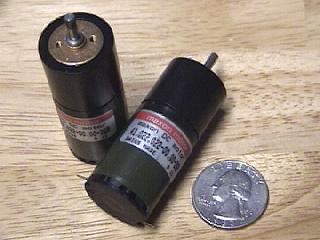
I found some Maxon gearheads that I had to put to use somehow so I started putting another base together. I'm calling it Max Bot after the gearheads for no better reason. You can see it's progress below.
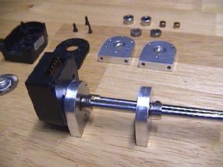
The only drawback was the Maxon's didn't come with encoder feedback, which was something I wanted on this robot. I was able to salvage some HP encoders from a pair of larger motors I had.Here are the axles and bearing mounts I mounted them to which I made on my Sherline CNC.
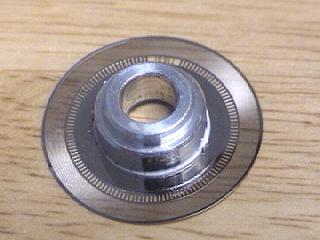
Here's a closeup of the encoder disc. The encoders are 512 CPR or 2048 CPR in quadrature.
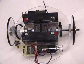
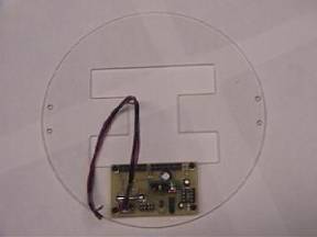
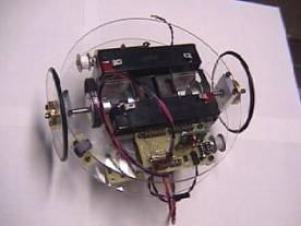
This is the lower level of the bot showing the motors and axle assemblies mounted. I left the motors far enough apart so there would be room to mount the 2 6v gel cells. The base is 6.75" diameter and the wheels are 3" diameter. You can see the 754410 hbridge board mounted next to the Maxon gearhead and a charge plug is mounted to the left of that. The hbridge has since been replaced with an Allegro hbridge as you can see below.
This is the second layer with the cutout for the encoders and batteries. This will help hold the batteries in place. Also shown is the power distribution board I started with. It has also been replaced with a more compact version.
One more change I made is the new outer bearing mounts. I decided to make them square on top so I could use them to mount the second layer instead of using standoffs.
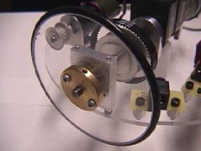
Here's a close up of the wheel detail showing the bearing mount with the threaded top to mount the second layer and another shot with the second layer in place.
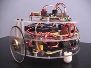
The third layer is cut out and installed with the 68332 MRM processor mounted to the top. As shown below Max Bot weighs in right at 3 pounds. This is one of Mark Castelluccio's earlier version boards.
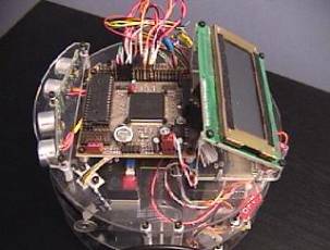
Here's a better shot of the MRM mounted on the top layer along with the addition of the 4 x 20 LCD.
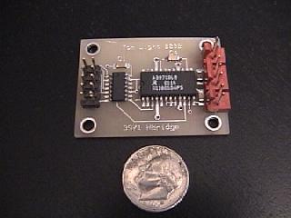
This is my Allegro 3971 hbridge board I'm using now.
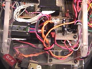
Just above the hbridge is the smaller power distribution board I'm using for the sensors etc. You can almost see the National Eval switcher mounted to the bottom side of the board. Beside it is a Powertrends switcher for the MRM itself. I'm currently not using the regulator on the MRM. Both of these are tucked away under the LCD display.
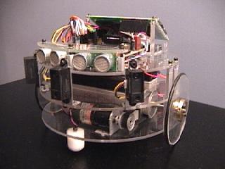
I've been testing several sensor arrangements so things don't stay mounted in one place for long. Here are the Devantech sonars and some Sharp GP2D02 IR detectors I'm testing. The IR detectors seem to work well where they are mounted now.
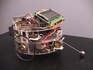
Here are the latest changes to Maxbot. Notice the skids are gone. I've added an external SPI interfaced 12bit A/D chip eventually for a gyro. Right now I've got it wired to a pot and am experimenting with some balance code which is working pretty good right now. It will right itself from a stopped position, but it only has to move around 15-20 degrees. The base needs to be reworked for this so it will tilt more. Once I get it fine tuned with a pot, I'll invest in a gyro - accelerometer combination of some type.

Here's a closer shot of the pot with the arm extending out. That's a ball bearing soldered to the wire. It probably would have been better to mount the pot under the base at the centerline, but there wasn't room. It still works fine.