Indoor: (F) / -17.8 (C)
How To
- Main HomePage
- Main HowTo Page
- LED Blink - Delay
- LED Blink - Int.
- PWM Output
- RS232 Output
- A/D Conversion
- A/D PWM Control
- Using Avrdude
Links
Atmega 48 88 168 PWM
Things you will need:
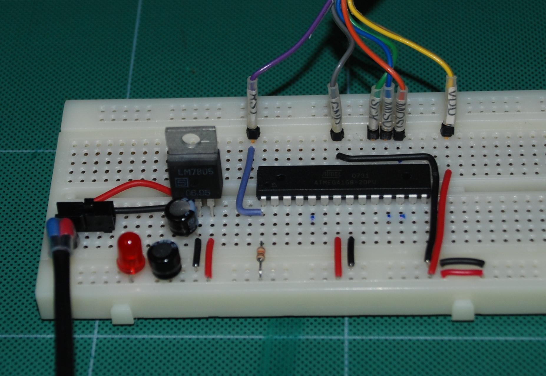 |
The breadboard setup as shown on the main page | 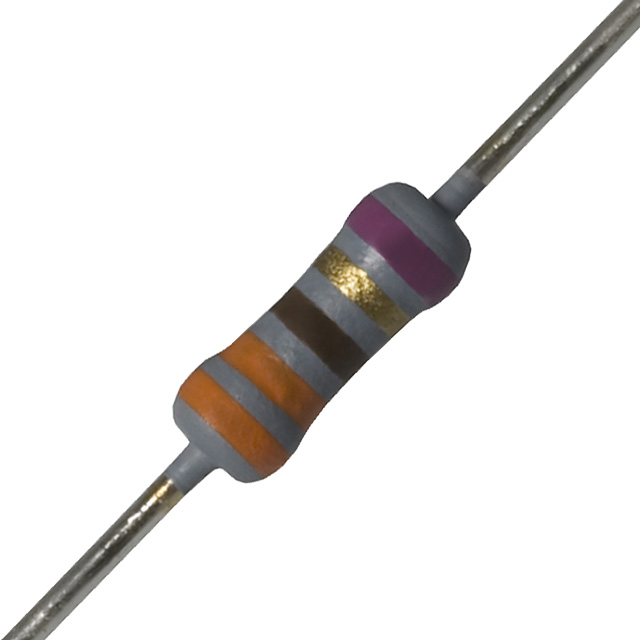 |
A 330 to 470 ohm resistor |
 |
A led |
||
* * * * * * * * * * * * * * * * * * * * * * * * * * * * * * * * * * * * *
1) Take the breadboard assembled from the main tutorial page and set it in front of you.

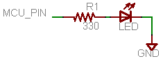
2) Connect the resistor with the led to PD6 (12) on the Atmega and to GND as shown in the schematic. The flat side of the led (cathode) goes to negative.
The result should be something that looks similar to below.
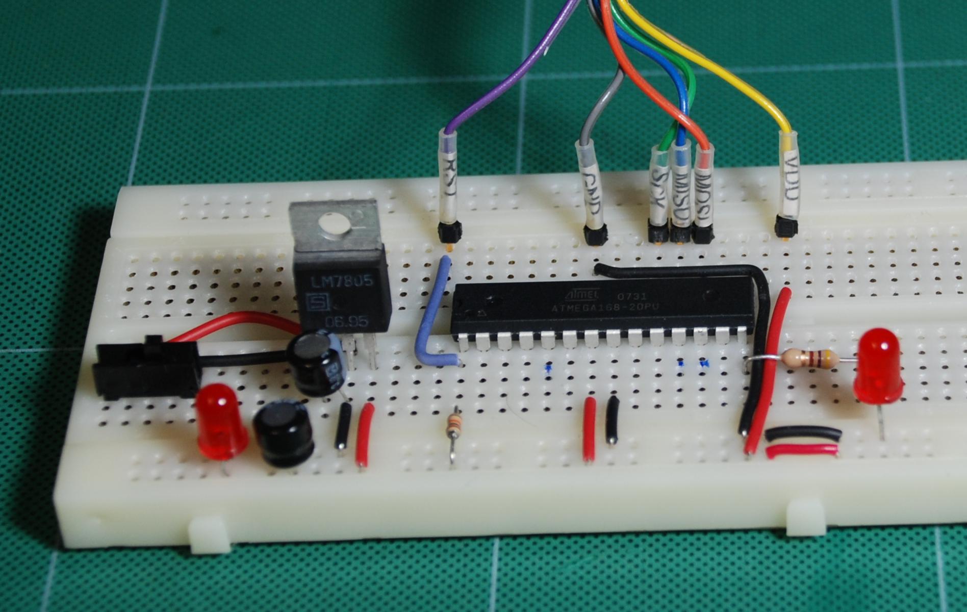
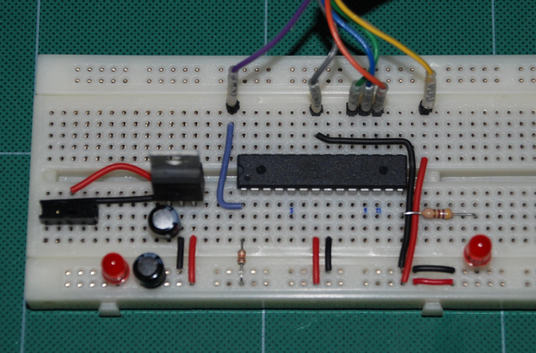
The ISP programmer hookup can be seen at the rear.
3) Download the following sample code and load it into the Atmega using your favorite download software. The specifics of programming the Atmega are not covered here since there are several different ways to do it.
4) Program the fuse settings as follows:
lfuse = 0x62, hfuse = 0xDF, efuse = 0xF9
C Example Code Section
/* basic pwm on a atmega168
8 bit PWM test on TIMER 0
disclaimer: use at your own risk.
Written by Tom_L */
# define F_CPU 1000000UL // 8Mhz internal OSC with
// div8 fuse set on mega168
#include <avr/io.h>
#include <util/delay.h>
#include "pwmtest.h"
int main (void)
{
DDRD = _BV(PD5) | _BV(PD6); // Set Timer 0 pins as outputs
pwm_init();
while (1) // Repeat forever
{
unsigned char x; // Just a temp count var.
for (x = 255; x != 0; x--)// loop thru
{
pwm_duty(x,x);
_delay_ms(100);
}
for (x = 1; x != 255; x++)// loop thru
{
pwm_duty(x,x);
_delay_ms(100);
}
}
}
void pwm_duty(unsigned char dutyA, unsigned char dutyB)
{
OCR0A = dutyA; // Timer0 output compare A
OCR0B = dutyB; // Timer0 output compare B
}
void pwm_init()
{
// clear pwm levels
OCR0A = 0; // PD6 pin12 Timer0 output compare A
OCR0B = 0; // PD5 pin11 Timer0 output compare B
// set up WGM, clock, and mode for timer 0
TCCR0A = 1 << COM0A1 | /* not inverted */
0 << COM0A0 |
1 << COM0B1 | /* not inverted */
1 << COM0B0 |
1 << WGM01 | /* fast pwm */
1 << WGM00 ; /* fast pwm */
TCCR0B = 0 << FOC0A |
0 << FOC0B |
0 << WGM02 | /* fast pwm */
1 << CS02 | /* div 256 prescale */
0 << CS01 |
0 << CS00 ;
}
C Source code for this project.