Indoor: (F) / -17.8 (C)
How To
- Main HomePage
- Main HowTo Page
- LED Blink - Delay
- LED Blink - Int.
- PWM Output
- RS232 Output
- A/D Conversion
- A/D PWM Control
- Using Avrdude
Links
Atmega 48, 88, 168 How to series
This is a tutorial of simple projects intended to teach a complete noob how to use the Atmega 8bit controllers. The chips chosen were the Atmega 48, 88 and 168. If you are completely new to them, you should follow the tutorials in order.
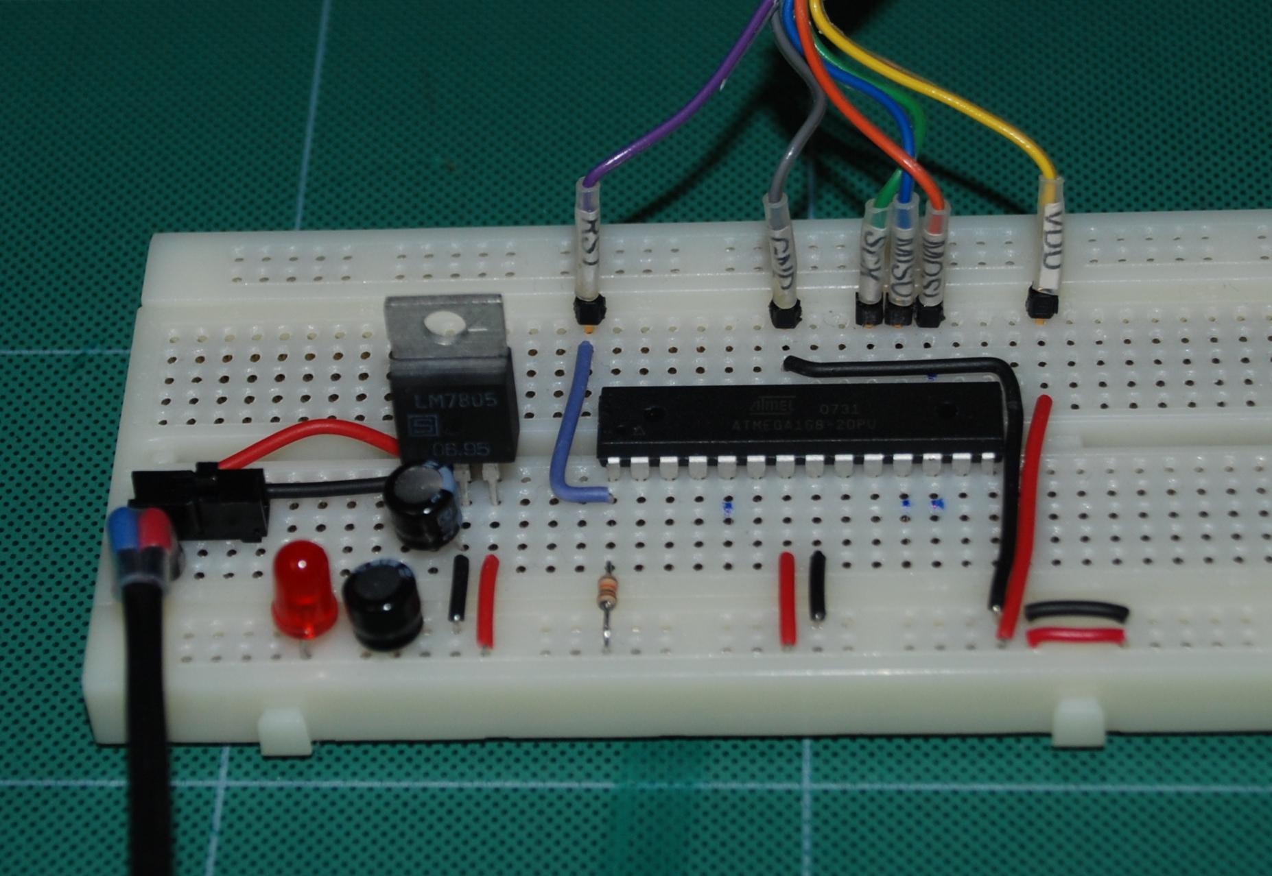
This will be the basic setup throughout this series. Components will be added as required to complete each tutorial. Lets get started and put together the basic parts for our tutorials.
Things you will need:
 |
A 9 to 12v dc regulated supply |  |
A 7805 regulator |
 |
A couple 10 - 100uf electrolytic caps |  |
A breadboard |
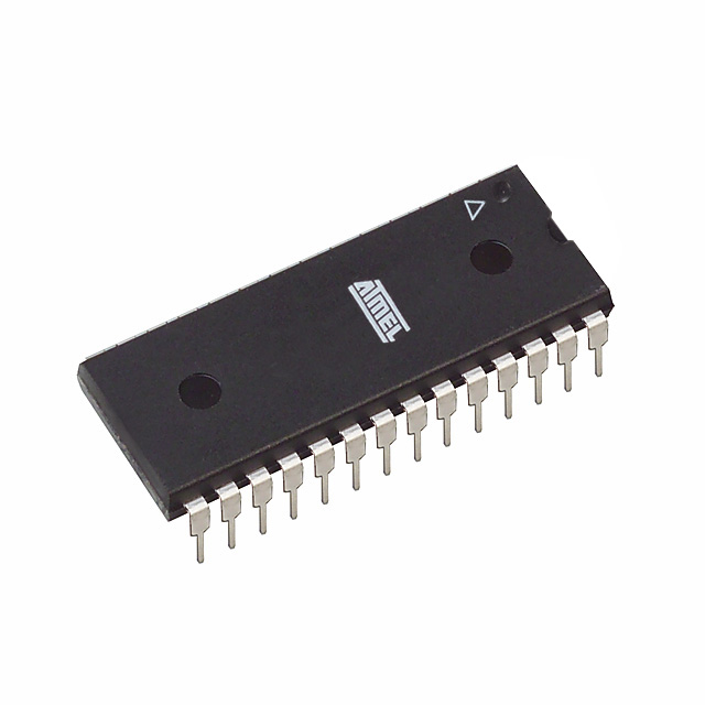 |
An Atmega 48 88 or 168 | 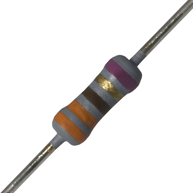 |
A 330 ohm resistor and a 10K resistor |
 |
A led |  |
A SPDT slide or toggle switch |
|
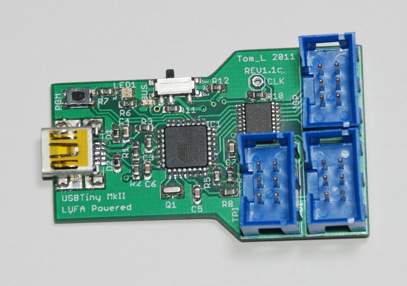
An ISP programmer | And some solid hookup wire | |
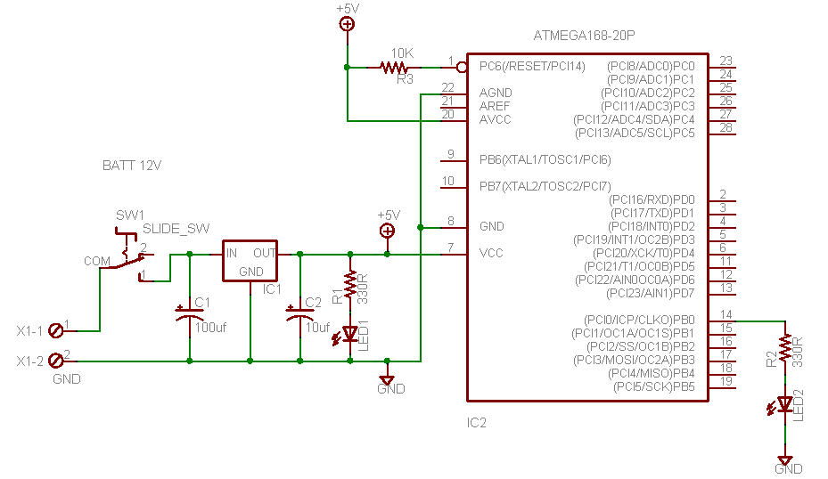
1) Take the breadboard and wire up the 5v regulator as shown below. Place an electrolytic capacitor on each side of the regulator as shown in the schematic. The white stripe on the capacitor is the negative side as shown in the table above. Connect the positive lead of one of the capacitors to the regulator input and the positive lead of the other one to the regulator output. The inputs will connect to the DC regulated walwart.

2) Insert the slide switch into the breadboard.
3) Run a wire from the center lead of the switch to the input pin of the regulator.
4) Run a wire from the GND wire of the walwart to the GND pin on the regulator.
5) Wire the positive side of the walwart to one of the side leads of the slide switch.
6) Place the Atmega chip in the breadboard so the pins straddle the center of it.
7) Wire the GND pins (8 and 22) to the GND on the regulator.
8) Wire the VCC pin (7) to the OUT on the regulator.
9) Wire the 10k resistor from RESET (1) to +5v as a pullup for the reset line.
10) Connect a lead of the 330 ohm resistor to +5 and the other lead to the led as shown in the diagram. The flat side of the led (cathode) goes to negative.
An ISP programmer will be used in this tutorial.
The next step is to add wires to the breadboard to connect to it. The wires for that are shown at the rear of the breadboard and have been labelled. The following connections should be made.
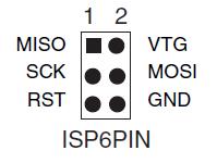
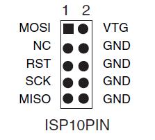
MOSI to PB3 (PIN 17)
MISO to PB4 (PIN 18)
SCK to PB5 (PIN 19)
RST to PC6 (PIN 1)
+5v to the +5v rail
GND to the GND rail
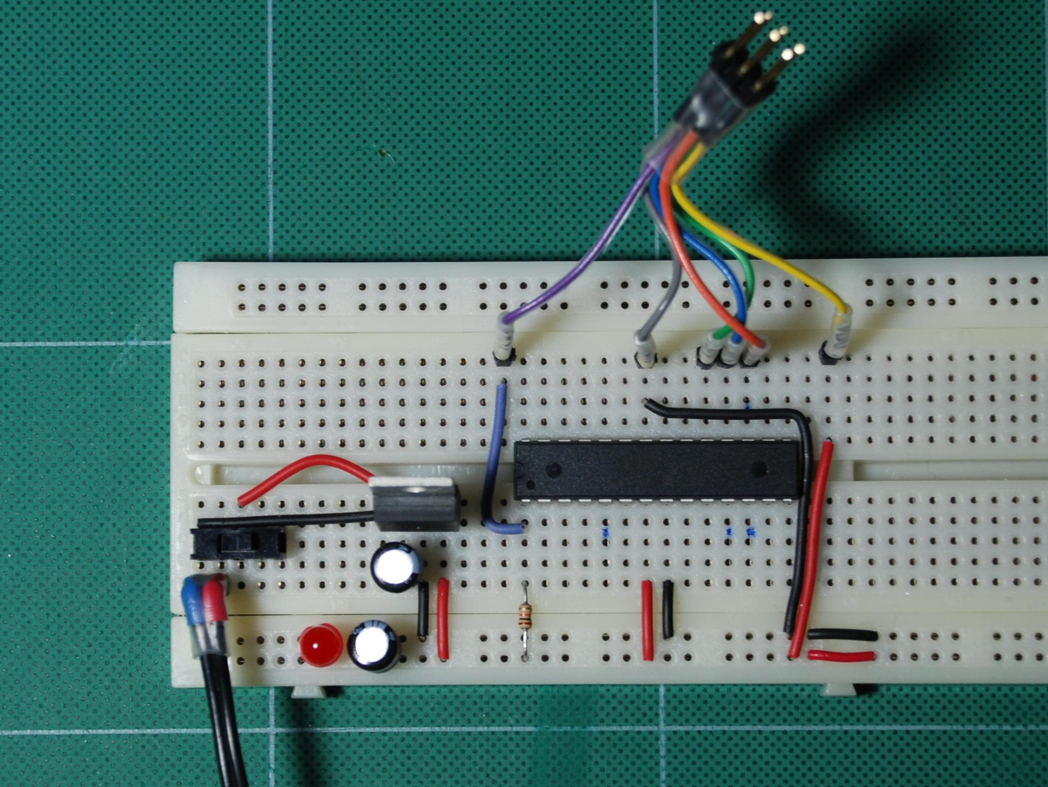
The basic breadboard setup should look similar to this. Refer to this page for the basic setup for the other tutorials.