Indoor: (F) / -17.8 (C)
How To
- Main HomePage
- Main HowTo Page
- LED Blink - Delay
- LED Blink - Int.
- PWM Output
- RS232 Output
- A/D Conversion
- A/D PWM Control
- Using Avrdude
Links
A / D on Atmega 48, 88, 168
Things you will need:
1) Take the breadboard assembled from the main tutorial page and set it in front of you.
2) Connect one lead of the 1K resistor to AREF (21) and the other lead to +5v for a reference voltage.
3) Connect a wire from AVCC (20) to VCC (+5). (For better noise immunity there should be an inductor between AVCC (20) to VCC but for this test a wire is being used.)
4) Connect one lead of the .1uf capacitor to AVCC (20) and the other lead to GND.
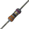
5) Solder a short lead on each of the lugs on the pot as shown.
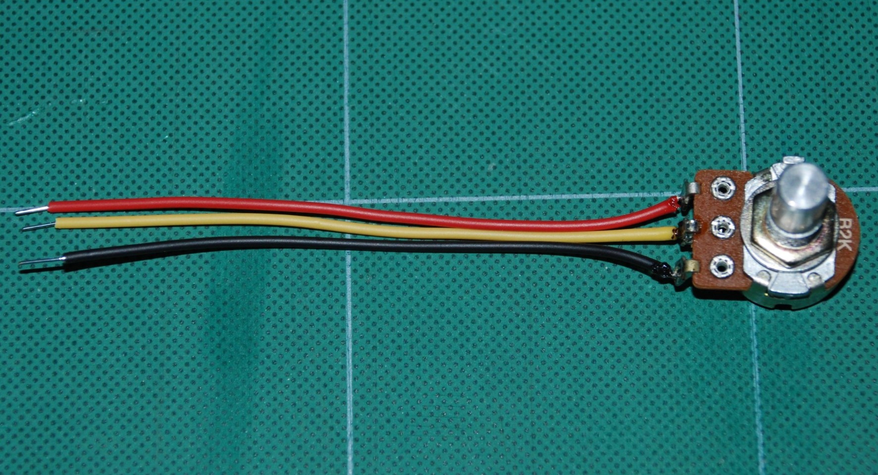
6) Connect the 220 ohm resistor to PC2 (25) on the Atmega and to an open pad on the breadboard. The resistor will help prevent a direct short to the adc pin should something crazy happen.
7) Wire the center lead of the pot to the open end of the 220
ohm resistor and one of the other leads to +5v and
the other lead to the GND rail on the breadboard as shown.
8) Wire up the RS232 converter as layed out in the RS232 tutorial.
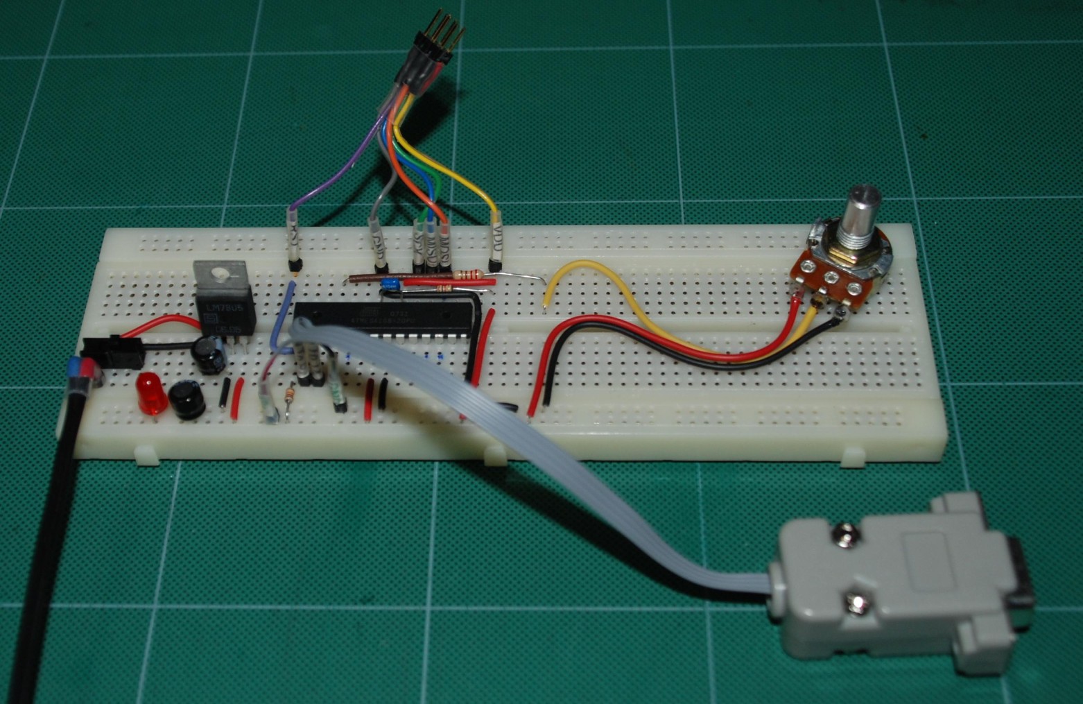
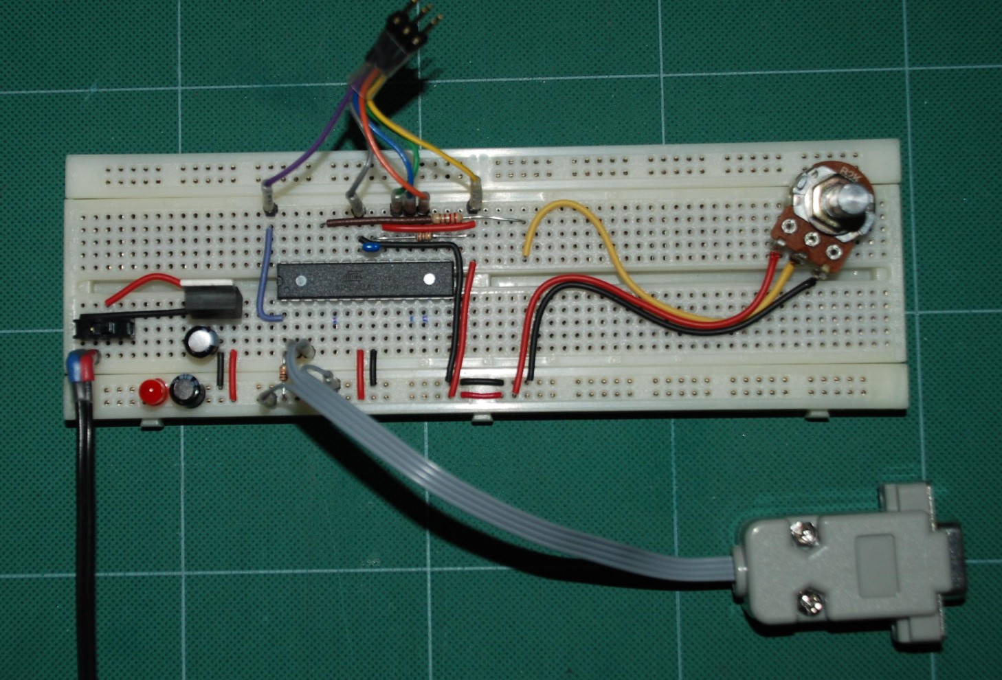
The setup should be something that looks similar to below.
The ISP programmer hookup can be seen at the rear.
9) Download the following sample code and load it into the Atmega using your favorite download software. The specifics of programming the Atmega are not covered here since there are several different ways to do it.
10) Program the fuse settings as follows:
lfuse = 0x62, hfuse = 0xDF, efuse = 0xF9
When the program is loaded and run, similar results should be seen in the terminal window. As the pot is turned, the values will increase or decrease.
C Example Code Section
/* ADC Test
For an Atmega 48 88 or 168
Sends ADC results to the serial port
Set your terminal to 2400 N 8 1
Atmega168 DIP TX PD1 (pin3)
Atmega168 DIP RX PD0 (pin2)
Atmega168 DIP ADC2 PC2 (PIN25) */
#define F_CPU 1000000UL
#define UBRR_1200 51
#define UBRR_2400 25 // for 1Mhz
// #define UBRR_2400 207 // for 8Mhz with .2% error
// #define UBRR_9600 51 // for 8Mhz with .2% error
// #define UBRR_19200 25 // for 8Mhz with .2% error
#include <avr/io.h>
#include <util/delay.h>
#include <stdio.h>
void read_adc(void); // Function Declarations
void adc_init(void);
void USART_init( unsigned int ubrr );
void USART_tx_string( char *data );
volatile unsigned int adc_temp;
char outs[20];
int main(void)
{
adc_init(); // Initialize the ADC
USART_init(UBRR_2400); // Initialize the USART
USART_tx_string("Connected!\r\n"); // we're alive!
_delay_ms(125); // wait a bit
while(1)
{
read_adc();
snprintf(outs,sizeof(outs),"%3d\r\n", adc_temp); // print it
USART_tx_string(outs);
_delay_ms(125); // wait a bit
}
}
/* INIT ADC */
void adc_init(void)
{
/** Setup and enable ADC **/
ADMUX = (0<<REFS1)| // Reference Selection Bits
(1<<REFS0)| // AVcc - external cap at AREF
(0<<ADLAR)| // ADC Left Adjust Result
(0<<MUX2)| // Analog Channel Selection Bits
(1<<MUX1)| // ADC2 (PC2 PIN25)
(0<<MUX0);
ADCSRA = (1<<ADEN)| // ADC ENable
(0<<ADSC)| // ADC Start Conversion
(0<<ADATE)| // ADC Auto Trigger Enable
(0<<ADIF)| // ADC Interrupt Flag
(0<<ADIE)| // ADC Interrupt Enable
(1<<ADPS2)| // ADC Prescaler Select Bits
(0<<ADPS1)|
(1<<ADPS0);
// Timer/Counter1 Interrupt Mask Register
TIMSK1 |= (1<<TOIE1); // enable overflow interrupt
TCCR1B |= (1<<CS11)|
(1<<CS10); // native clock
}
/* READ ADC PINS */
void read_adc(void)
{
unsigned char i = 4;
adc_temp = 0;
while (i--)
{
ADCSRA |= (1<<ADSC);
while(ADCSRA & (1<<ADSC));
adc_temp+= ADC;
_delay_ms(50);
}
adc_temp = adc_temp / 4; // Average a few samples
}
/* INIT USART (RS-232) */
void USART_init( unsigned int ubrr )
{
UBRR0H = (unsigned char)(ubrr>>8);
UBRR0L = (unsigned char)ubrr;
UCSR0B = (1 << TXEN0); // Enable RX, TX & RX interrupt
UCSR0C = (3 << UCSZ00); //asynchronous 8 N 1
}
/* SEND A STRING TO THE RS-232 */
void USART_tx_string( char *data )
{
while ((*data != '\0'))
{
while (!(UCSR0A & (1 <<UDRE0)));
UDR0 = *data;
data++;
}
}
C Source code for this project.
