Back
[01:38:02] <Jak_o_Shadows> Gyroscope arrived
[01:41:56] <mrdata> \o/
[12:37:07] <EastsideR> evening
[12:42:30] * z64555 researches variacs
[12:43:08] * EastsideR works on path planning with a-star and maps with quad tree decomposition
[12:43:21] <EastsideR> don't think I can knock this off in 48 hours
[12:44:36] <EastsideR> either way I am stuck thinking of a good herusitics for quad tree maps because it doesn't seem to be done before.
[12:45:00] <EastsideR> oh there's one on youtube
[12:47:01] <z64555> hm, I might actually have an old variac somewhere. would be good to use it instead of making one myself
[12:54:46] <z64555> oh. hm. I don't know if it'll have sufficient current throughput, though
[13:06:49] <z64555> heh, I might be better off just using a car battery for this
[13:18:49] <z64555> Welding time will be short, but I don't need to weld up a large piece
[13:35:12] <z64555> hm
[13:35:41] <z64555> looks like i can make a plasma torch out of it, too, using a pencil
[13:35:51] <z64555> as the electrode
[13:39:42] <z64555> dad had a neat carbon arc lamp he made out of a tin can, a pencil, and some lamp cord
[13:40:28] <robotustra> uF is for microfarads
[13:40:30] <z64555> I think he used two pencils, though, or something. If the can acted as the anode it would've been toast
[13:40:34] <robotustra> hi
[13:40:54] <robotustra> how is everything?
[13:40:56] <z64555> well, the actual symbol is mu, but mu isn't in ascii. so u is acceptable
[13:41:18] <robotustra> it was sarcasm actually :)
[13:41:24] <z64555> good over here, I'm getting my McGyver on today.
[13:41:40] <robotustra> what is this?
[13:42:14] <z64555> hm?
[13:43:04] <robotustra> McGyver is a man?
[13:43:19] <z64555> McGyver was a TV show, its titular character was known of making interesting hacks with common objects
[13:43:31] <z64555> recently there was a reboot of the series
[13:43:35] <robotustra> ok, I don't watch TV sorry
[13:43:45] <z64555> yes, but you can google. :)
[13:44:25] <robotustra> I googled and it's not seems more interesing that real life :)
[13:45:00] <z64555> Perhaps for you, but around here, inventive people are rare
[13:45:27] <robotustra> I can't stand for opposit
[13:45:38] <robotustra> not much really
[13:45:55] <robotustra> I got my up-board
[13:46:22] <robotustra> and it seems to me it's much better than edison
[13:46:25] <z64555> anyway. I was looking at the possibility of making a crude arc welder (SMAW) and a plasma torch
[13:46:33] <z64555> hence the reference
[13:46:56] <robotustra> welding machine?
[13:47:59] <robotustra> I did one in my childhood
[13:48:22] <robotustra> 2 thoroidal trasformers
[13:49:02] <robotustra> do you want AC or DC welder?
[13:49:38] <z64555> whatever works, preferably with the least amount of effort to get something workable and safe
[13:49:44] <z64555> which turns out to be a car battery.
[13:49:45] <z64555> :)
[13:50:09] <z64555> I'll try taht first, but if I need more welding time, I'll look into building an AC machine
[13:50:23] <robotustra> yeah, 2 car batteries is enouph to weld
[13:50:49] <robotustra> it depends on what is better
[13:50:49] <z64555> the up-board does look like it's better suited for experimentation than the edison board
[13:51:33] <robotustra> I did weld with AC but you should have good welding rods
[13:51:50] <z64555> I generally have better luck with DC welding. It has a continuos power transfer vs. AC whose power varies over time
[13:51:57] <robotustra> edison is just not stable for power strikes
[13:52:13] <z64555> power strikes?
[13:52:25] <robotustra> power downs
[13:52:36] <robotustra> power blackout
[13:53:40] <z64555> they're both intel atoms, but the up-board has a newer version
[13:53:42] <robotustra> I had it connected to the robot chassy and when I move it turned off the motors give enouph of energy to power up the edison
[13:54:00] <robotustra> I think the problem is in th file system or flash
[13:54:17] <robotustra> I killed edison 3 times in a half of year
[13:54:37] <robotustra> by unappropriate switching off
[13:54:41] <z64555> uh. try that sentance again, I didn't understand how the edison powered up
[13:55:07] <robotustra> motors give the power
[13:55:20] <robotustra> when I drug the chassy
[13:55:32] <robotustra> like generators
[13:56:07] <robotustra> when I pull the robot - the motor became a generator - is it clear?
[13:56:31] <z64555> right. should probably make some sort of isolation circuit
[13:56:31] <robotustra> becomes*
[13:56:52] <z64555> How are the motors connected to the board?
[13:57:05] <robotustra> through the driver
[13:57:14] <robotustra> but it's workaround
[13:57:34] <robotustra> I can put relays to disconnect motors
[13:57:48] <z64555> what is your motor driver?
[13:57:52] <robotustra> when it's powered off
[13:58:08] <robotustra> pololu drivers
[13:58:17] <robotustra> like A88**
[13:58:52] <robotustra> 12 V 1 A or so
[14:00:15] <robotustra> A4988
[14:00:19] <z64555> maybe stick a diode on the positive terminal of the driver to prevent backflow.
[14:00:22] <z64555> hm. wait, no
[14:01:24] <robotustra> there protection diods i nthe circuit already
[14:01:24] <z64555> I'm assuming you have a master power switch on one of the terminals to the battery
[14:01:48] <robotustra> that's what I'm going to do
[14:01:58] <robotustra> put more relaus
[14:02:01] <robotustra> relays
[14:02:02] <z64555> nah
[14:02:08] <z64555> use a DPDT switch
[14:02:28] <robotustra> to turn it on manually?
[14:02:39] <z64555> put the drivers on one pole, everything else on the other pole
[14:02:50] <z64555> that'll isolate the drivers from the other circuitry
[14:03:40] <robotustra> actually, it's not a problem for me, I think that the board should be isolated when it's off
[14:04:03] <z64555> you'll have two throws open, and the other two throws connected to the battery
[14:05:05] <z64555> well it is a problem for you. When you move the motors it acts as a generator. Thus, if the driver's are connected to the board, they'll act as a power souce
[14:06:10] <z64555> using relays, diodes, etc. to provide isolation will work, but it adds complexity, reduces durability, more power loss, and is more expensive
[14:06:30] <robotustra> yes, may be I'll put relays AFTER drivers
[14:06:42] <robotustra> http://pastebin.com/ZxtZG4VD
[14:06:50] <robotustra> current ciruit
[14:07:19] <z64555> :(
[14:07:37] <robotustra> :)
[14:07:43] <z64555> I applaud your ASCII art skills, but why arn't you using a schematic program, such as LTSpice?
[14:08:34] <robotustra> because I put these ascii arn in my arduino sketches
[14:08:43] <veverak> cool idea
[14:09:08] <robotustra> graph schematic is for loosers ;-)
[14:09:31] <mrdata> lol
[14:09:36] <theBear> lol, old school ! alt.robotics.asciiart
[14:09:54] <robotustra> there is a programm to draw such scematic
[14:10:19] <z64555> in ascii style?
[14:10:32] <robotustra> yes
[14:10:46] <z64555> k.
[14:10:46] <robotustra> AACircuit1_28_6
[14:11:01] <z64555> well
[14:11:26] <z64555> lemme make an illustration of that DPDT idea I had earlier
[14:11:43] <robotustra> when I have this schema inside my .ino file - I'll never loose it
[14:12:47] <robotustra> I have some relays with dpdt
[14:13:09] <robotustra> small ones
[14:17:31] <z64555> http://pastebin.com/BbqyP8sT
[14:17:40] <robotustra> now I'm working on this circuit
http://pastebin.com/cuX9ix5w
[14:18:17] <z64555> if you have a DPDT relay, you can use one to fully isolate each motor
[14:18:30] <z64555> so 1 motor, 1 relay
[14:18:52] <z64555> hm
[14:18:57] <z64555> in fact
[14:19:00] <robotustra> I got your idea
[14:19:08] <z64555> making a modification to it
[14:19:32] <robotustra> 1 relay to disconnect + from everything
[14:22:31] <z64555> ok, updated the past
[14:22:35] <z64555> *paste
[14:23:20] <robotustra> Rm is a pull down&
[14:23:30] <robotustra> ?
[14:23:38] <z64555> yeah
[14:24:00] <z64555> so when you have the switch "off" any power generated by the motors is transfered into heat at the resistor
[14:24:31] <z64555> might be safer than just leaving the motors open. not sure
[14:24:37] <robotustra> you see - we already can exchange with schematic by using simple text editor - no matter what OS you are running
[14:24:54] <robotustra> yep
[14:25:10] <z64555> I can just as easily do this in MS paint, as well. :P
[14:25:43] <robotustra> yes you can, but can't see it in a text editor
[14:26:03] <robotustra> you need _SPECIAL_ software :)
[14:26:19] <theBear> edison tx/rx ? what's a edison
[14:26:24] <z64555> MS Paint is common to all windows operating systems
[14:26:29] <theBear> you need sensible fonts
[14:26:36] <robotustra> I'm running debian
[14:26:41] <z64555> theBear: It's intel's breakout board for the intel Atom
[14:26:42] <theBear> i haven't had windows since '04
[14:26:57] <theBear> z64555, no shit ? that sounds kinda fun
[14:27:10] <robotustra> me too, debian/linux since 2000
[14:27:18] <theBear> what kinda atom we talking, old 400-ish number models or fancy new ones ?
[14:27:48] <robotustra> theBear:
https://en.wikipedia.org/wiki/Intel_Edison
[14:27:51] <z64555> that's kinda splitting hairs. "Paint" is a common program used to make .bmp's and maybe even a .gif
[14:27:54] <theBear> robotustra, oh i been slack and redhat since the earliest days to various extents, but hot damn i been happy since i got rid of the last annoying windows mess in the house :)
[14:27:56] <robotustra> but don't buy it
[14:28:07] <theBear> we don't have paint, believe it :) not to mention macs
[14:28:22] <theBear> oh theBear doesn't buy stuff, he waits till someone breaks/replaces/doesn't want stuff
[14:28:48] <z64555> or any generic raster art program
[14:28:52] <theBear> heh, 4gb flash, that beats the hell outta early netbooks
[14:28:59] <robotustra> I'm already at the level of OS using that there is no difference form me which OS to use. I just don't care :)
[14:28:59] <z64555> probably called "draw" or whatever
[14:29:17] <robotustra> I have "display"
[14:29:26] <robotustra> "GIMP" etc
[14:29:59] <z64555> GIMP is rather overkill, and is rather poor for image creation like with schematics
[14:30:22] <robotustra> I cat use different pic formats, but text is much easier and faster
[14:31:04] <theBear> shccematics you want a purpose built something, and if we talkin gimp vs paint, gimp has a bunch of stuff that'd make it easier, but it's like arguing if a chainsaw or a tablesaw is better at slicing up a loaf of bread, they're both silly things to use :)
[14:31:17] <veverak> nah
[14:31:22] <veverak> as for portability and universality
[14:31:29] <veverak> you can't beat ASCII chart really
[14:31:37] <veverak> (As long as it is reasonably able to show the circuit)
[14:32:29] <robotustra> to share pic with people there are plenty of web drawing tools like
http://flockdraw.com/
[14:32:46] <robotustra> but again, I like ascii art
[14:32:57] <robotustra> it's just IMHO
[14:33:16] <robotustra> I go back to simple things
[14:33:18] * veverak would export to png propably from the app he uses
[14:33:50] <z64555> I'd feel like smacking somebody if they did an ascii schematic on a .png
[14:33:56] <z64555> :P
[14:34:41] <veverak> z64555: I was talking about normal circuit :D
[14:34:54] <z64555> the line breaks are distracting, and in densely drawn areas it's difficult to trace the connections
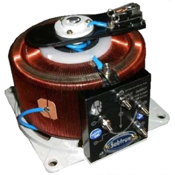
[14:35:23] <robotustra> do you have some autotransphormers?
[14:35:54] <veverak> because
[14:35:58] <veverak> you can always printscreen the thing
[14:36:09] <robotustra> like these?
http://www.electronicshub.org/wp-content/uploads/2015/01/Variable-Auto-transformer.jpg
[14:36:09] <veverak> so some sort of .png would work for me propably
[14:36:20] <veverak> :)))
[14:36:25] <z64555> I have a wire-wound potentiometer laying around somewhere that can act as an auto-transformer.
[14:37:05] <robotustra> I did a welder from 2 like these
[14:37:22] * z64555 looks at link
[14:37:27] <z64555> Yeah, it looks just like that
[14:37:33] <z64555> except without the center tap
[14:37:37] <robotustra> you need 2
[14:37:48] <robotustra> to make a welder
[14:38:39] <z64555> why two?
[14:39:43] <z64555> you can use a simpler auto-transformer (non-variable) in series
[14:40:13] <robotustra> 1) take off primary, 2) wind this primary on both transphormers evenly 3) wind a secondary with a thick aluminum wire, with a big cross section. 4) connect it in parallel but make sure in right phases
[14:40:20] <robotustra> welder is ready
[14:41:03] <z64555> huh
[14:41:06] <z64555> ?
[14:41:19] <z64555> with an autotransformer, there only is a primary
[14:42:54] <robotustra> what is the diameter of your welding rod?
[14:43:37] <robotustra> yes it is, it's primary, but you have to spread this wire on two cores
[14:44:18] <robotustra> 1) to dissipate heat 2) to be able to wind secondary 3) to increase the cross section of the core
[14:44:42] <robotustra> and you can weld with 3mm welding rod
[14:44:56] <robotustra> I mean the metal part of welding rod
[14:45:01] <z64555> simply connecting the two variacs in series isn't sufficient, I guess?
[14:45:30] <robotustra> no, because you'll need to wind too much secondary
[14:45:47] <robotustra> and it' will not just fit into the hole
[14:47:33] <robotustra> you need to get about 40V on the secondary
[14:47:59] <robotustra> I did this transphormer for 220V
[14:48:34] <robotustra> if you'll make it for 115 it will be different number of turns
[14:49:45] <z64555> is your design still variable?
[14:50:02] <z64555> that is, you can still change the inductance/ transformer ratios during operation?
[14:50:55] <robotustra> no
[14:50:59] <robotustra> you cant
[14:51:20] <z64555> ok
[14:51:30] <robotustra> to change the current/voltage you need to do offsprings on the secondary
[14:51:42] <robotustra> it's the simplest way
[14:51:49] <theBear> 110-ish volts rewinds or i spose alternate-designs always seem to end up a little bigger than 240-ish volt ones, i spose cos of the old current vs wire size doesn't care about voltage thing
[14:52:40] <robotustra> make 2-3 offsprings and you'll adjust your voltage and current for any welding rod
[15:13:46] <z64555> still trying to figure out how leakage inductance that dual-core design has
[15:16:31] <theBear> dual core ? you mean like a cheap arc welder with split transformer ? cos i thinkin that would go from 100% transformer/0%ish inductor to quite a bit the other way, maybe i dunno 50% transformer and 50% inductor, and leakage isn't really the right term, more inherant or err, parasitic maaaaybe
[15:18:56] <z64555> I think it's more of a 25/75 distribution, since you have the same length of wire as on the first core, but is wound about both cores
[15:19:23] <z64555> that's my hipshot guess, though
[15:23:33] <theBear> the umm, i think you don't mean a split varying-gap 2-halves transformer like i talkin bout
[15:23:59] <z64555> no, still talking about robotustra's design
[15:24:51] <z64555> it has 2 cores of same material and dimensions.
[15:25:20] <z64555> one core has windings directly against it, the other is "lashed" to the first core with the rest of the winding
[15:26:06] <z64555> the number of windings that are common to both cores appears to be 2/3's that of the number of windings on the first core
[15:26:48] <z64555> (a little less than 2/3's in physical realization)
[15:27:41] <z64555> here's how I found that out: Take two squares of equal size. They have a side length s, and a circumferance C
[15:28:06] <z64555> each C is 4s.
[15:28:21] <z64555> If you join them together, the resulting rectangle has a C of 6s
[15:29:29] <z64555> a single winding of the first core would have a length 4s. If you were to wrap it around the second core, it would go around 2/3's of the way
[15:29:44] <theBear> hmmmm.... why 2 cores ?
[15:30:40] <robotustra> to increase the heat dissipation?
[15:31:06] <z64555> presumably to make a leakage current, or some sort of in-series resistance or impedance to make it safe whenever a welding rod gets stuck
[15:31:50] <z64555> I doubt it has anything to do with heat dissipation
[15:33:12] <z64555> wires are insulated electrically, and thermally to an extent. Lashing the two cores together like that would make a poor thermal connection
[15:33:14] <robotustra> I see you are a pro in protection circuits, believe me, you don't need a protection circuit for that
[15:34:45] <z64555> when a rod gets stuck, you no longer have a load element. the coils are effectively shorted across each other
[15:35:02] <z64555> eh, wait, that didn't come out right
[15:35:19] <z64555> *the secondary coil is shorted
[15:36:14] <z64555> current is still flowing through the coil, and is only limited by the resistances and impendances by the coil itself. Thus, heat is generated on the coil
[15:36:47] <z64555> heat is also generated during normal use, but is distributed more across the load element (the open arc)
[15:40:19] <theBear> cores touching will work like a single core, but with bonus breaks a la laminations which is good for eddy currents and crap like that
[15:41:20] <theBear> you don't get a softening effect till there's at least a tiny gap (can be only one "side" of the magnetic circuit, like a toroid with a slot cut somewhere, or err, ei with i guess a gap on either outside loop somewhere, or two entirely seperate cores NOT touching
[15:44:41] <z64555> the cores are seperated by the windings
[15:44:56] <z64555> of the first core. so they are isolated
[15:46:43] <z64555> so there are two B fields, one in each core
[15:47:36] <z64555> the first half of the winding (which is just on the first core) picks up one B field, the second half of the winding (which is on both cores) picks up both B-fields
[15:47:58] <z64555> picks up/generates/affected by/affects
[15:48:07] <z64555> hm. coupled might be the better term
[16:12:09] <z64555> ah, so there is leakage inductance
[16:12:41] <z64555> the the first half of the winding has a side that is common to both cores
[16:13:20] <z64555> the current going through that side generates a B-field in the opposite direction of the second half of the coil
[16:14:45] <z64555> the second half of the coil has a 3:1 advantage over this. _but_ there are less number of windings on the second half
[16:16:20] <z64555> this is for a square cross-sectional toriod
[16:17:20] <z64555> if the cross sections were circular or elliptical, this leakage coupling would be less
[16:22:20] <z64555> for square/rectangular cores, the effective windings formula would be ((3C_1 - C_12) / (C_12)) * N1
[16:22:49] <z64555> for the described transformer construct
[16:23:59] <z64555> which, if said cores where square. The effective ratio would be 2x
[16:24:25] <z64555> er, wait
[16:27:25] <z64555> no, that's not right
[16:27:34] <z64555> hm, will try to pick this up tomorrow
[16:30:00] <theBear> all transformers are coupled "inductors", tho they don't behave like it when they got a load conneted, and if the cores seperated by well, anything at all, they're just less effectively coupled to some extent, and kinda "soft" ... and "leakage inductance" just doesn't make sense and isn't a thing, you can't leak inductance, that's not how inductance works
[16:30:51] <theBear> tho i ain't all over my magnetics math yet so i can't confirm or deny yours, tho the explanation of your workings sounds plausible
[16:38:07] <z64555> leakage inductance is an impendance in the individual coils of a transformer. it is a degree of de-coupling between the two
[16:38:28] <EastsideR> hah I forgot all my power electronics math already :/
[16:39:41] <z64555> a clear example would be to have an ideal transformer, with an inductor in series with each side
[16:40:12] <z64555> those inductors are actually part of both windings of the transformer itself
[16:41:03] <z64555> but, for whatever reason, the B fields generated by the windings (the leaky inductors) are not shared between them
[16:42:39] <z64555> robotustra's trick for adjusting the voltage, by un-winding a few loops of the secondary coil and looping them outside of the cores, introduces leakage current at the same time of the intended reduction of effective windings around the core
[16:44:25] <z64555> likewise, a leakage inductance is generated between the two cores of the example, due to the reasons stated before
[16:44:39] <z64555> (where one side of the windings around the first core are in contact with the second core)
[16:45:35] <z64555> You could eliminate that leakage inductance if you figure-8 the second half of the winding, instead of the simple loop
[16:48:02] <z64555> but then you gotta worry about eddy currents sparking between the two cores
[16:48:06] <z64555> maybe
[18:00:24] <theBear> they're not leaky, they're just inductors
[18:00:56] <theBear> the transformer can be leaky, it can exhibit inductance/inductive qualities, but inductance/inductors don't leak inductance
[19:15:21] <z64555> since you seem to have missed this bit:
[19:15:22] <z64555> 4:09:29 PM - z64555: leakage inductance is an impendance in the individual coils of a transformer. it is a degree of de-coupling between the two
[19:16:41] <z64555> it's a measure of inefficiency, in henries vs. a %
[19:17:38] <z64555> an ideal transformer is 100% efficient in transferring power between the primary and secondary
[19:18:46] <z64555> the primary can have an efficincy in transferring electrical power into a magnetic field within the core
[19:19:33] <z64555> and the secondary can have an efficiency in transferring electrical power from the magnetic field of the core
[19:21:04] <z64555> In our example, the first half of the winding is nearly 100% efficient in transferring power into the first core
[19:21:32] <z64555> and is (perhaps) at best -25% efficient to transfer power into the second core
[19:22:09] <z64555> the negative here represents that the B field in the second core is opposite in direction of the B field in the first core