Back
[00:14:27] <rue_house> flyback, should I try to understand the crazy lunitic?, or just pretend he's not there?
[00:19:38] <flyback> I like to pretend I am not here also
[00:43:04] <Triffid_Hunter> anonnumberanon: you're generating servo pulses by polling the timer? why not use the output compare? it's perfect, you get single clock precision, ie whatever jitter the clock crystal has :P
[00:43:33] <Triffid_Hunter> anonnumberanon: I have a thing on github somewhere where I drive 16 servos using a single output compare and a 4514 line decoder chip
[00:43:52] <Triffid_Hunter> could trivially adapt it to use a 4017 decade counter or whatever else you like to break the clock signal out
[01:06:22] <rue_house> if
[01:06:49] <rue_house> a person were to set the clock freq such that 65536 cycles caused a 2.5ms rollover
[01:08:27] <rue_house> the 500us start would eat up 13107 counts
[01:09:00] <rue_house> there would be 52428 counts of resolution
[01:09:07] <rue_house> thats better than my 24000
[01:11:23] <rue_house> with no prescaler
[01:11:53] <rue_house> 26214400hz
[01:12:02] <rue_house> 26.214400Mhz
[01:12:10] <rue_house> ?
[01:12:26] <rue_house> that dosn't seem right
[01:12:51] <rue_house> 2.5ms
[01:13:07] <rue_house> divided by 65536
[01:13:26] <rue_house> .038us
[01:14:33] <rue_house> 262144Hz
[01:14:53] <rue_house> ...
[01:15:48] <rue_house> back to 26Mhz
[01:16:01] <rue_house> 2.5ms = .0025sec
[01:16:16] <rue_house> that gets chopped up into 65535 slices
[01:16:27] <rue_house> so .0025/65536
[01:16:40] <rue_house> and then we turn it over to make a freq out of it
[01:16:45] <rue_house> calc "1/(.0025/65536)"
[01:16:45] <rue_house> 1/(.0025/65536) -->> 2.62144e+07
[01:17:14] <rue_house> 2.62144e+07
[01:17:19] <rue_house> 26.2144e+06
[01:17:25] <rue_house> 262.144e+05
[01:17:32] <rue_house> 2621.44e+04
[01:17:38] <rue_house> 26214.4e+03
[01:17:43] <rue_house> 262144.e+02
[01:17:49] <rue_house> 2621440.e+01
[01:17:56] <rue_house> 26214400.e+00
[01:18:00] <rue_house> 26214400
[01:18:05] <rue_house> 26,214,400
[01:18:08] <rue_house> 26Mhz
[01:18:41] <rue_house> so with 16Mhz
[01:18:55] <rue_house> your max resolution, for 2.5ms
[01:19:37] <rue_house> 40000 counts
[01:19:54] <rue_house> then, if you subtract the 500us
[01:20:19] <rue_house> which is 8000 counts
[01:20:39] <rue_house> you would get 32000 counts of position resolution
[01:20:47] <rue_house> and my code has 24000
[01:22:34] <rue_house> wait a sec, I think my code only goes to 2ms
[01:23:22] <rue_house> zippo:/files/programming/c/router# calc 32000-8000
[01:23:22] <rue_house> 32000-8000 -->> 24000
[01:23:41] <rue_house> so, for a max of 2ms, my code IS as good as it gets without overclocking the avr
[01:23:54] <rue_house> thats why I have 24000 counts
[01:25:43] <rue_house> I suppose if I were crafty I could set the second timer to start the next pulse before the first one might have finished
[01:25:47] <rue_house> overlap the .5ms
[01:26:23] <rue_house> then that would mean i could fit 60Hz/1.5ms channels on the avr
[01:26:50] <rue_house> calc "(1/60)/(1.5/1000)"
[01:26:51] <rue_house> (1/60)/(1.5/1000) -->> 11.1111
[01:26:59] <rue_house> might as well just stay with 10 cahnnels
[01:30:21] <rue_house> but the world wants lots and lots of channels, and they dont care about resolution of jitter
[01:30:40] <rue_house> then they cant just use the 16 channel pwm controller on ebay
[01:30:55] <rue_house> gives them less than 6 bits of resolution with 16 channels.
[01:31:08] <rue_house> but they wont want to use extra chips
[01:31:30] <rue_house> can we make an avr do a WHOLE bunch of channels with,lets say 4 bits resolution?
[01:31:42] <rue_house> not without extra chips
[01:31:54] <rue_house> so, your locked to 16 channels on a m328
[01:31:59] <rue_house> yea
[01:32:31] <rue_house> why dont we do 4 bits and 16 channels
[01:32:43] <rue_house> at 4 bits...
[01:32:48] <rue_house> wait do 3 bits
[01:32:55] <rue_house> er, 3 counts
[01:33:11] <rue_house> 2ms, it divides by 500us into 4
[01:33:21] <rue_house> you can use the for loop glitch
[01:33:28] <rue_house> hmm
[01:33:47] <rue_house> you could use an 8 bit timer
[01:34:00] <rue_house> 16Mhz, rollover at 400hz?
[01:34:22] <rue_house> 2khz
[01:34:42] <rue_house> you could just software pwm it
[01:35:02] <rue_house> I'm gonna get some sleep
[01:35:17] <anonnumberanon> lol ye do tat
[01:35:19] <rue_house> if you put a 4017 on each of the 16 pins, you could get 160 channels
[01:35:45] <rue_house> dude, we should make a 160 channel, 3 bit servo controller
[01:35:47] <rue_house> hahahah
[01:35:57] <rue_house> left, center, or right hahahahahahha
[01:37:18] <anonnumberanon> haha
[01:37:28] <rue_bed> but 160 channels!
[01:37:39] <anonnumberanon> id need 160 cheap ass servos all bumped up togetherit can be done
[01:40:49] <anonnumberanon> Triffid_Hunter, yes I like the 4017 solution. I am trying to implement it as well.
[01:41:23] <Triffid_Hunter> anonnumberanon:
https://github.com/triffid/avr-servo may give you some ideas
[01:41:37] <anonnumberanon> Thanks!
[01:43:16] <Triffid_Hunter> anonnumberanon: although note that only two pins on the '328 are suitable for this technique - OCR1A and OCR1B but you can drive multiple servos from each one using external chips
[01:45:35] <anonnumberanon> Yes I've done some tests with this technique.
[01:45:54] <anonnumberanon> I didn't understand this pin issue completely.
[01:47:07] <Triffid_Hunter> anonnumberanon: the jitter-free timer output compare feature is only connected to specific pins. If you use interrupts or polling or any technique other than timer output compare, you will unavoidably get jitter of multiple cpu clocks
[01:47:48] <Triffid_Hunter> anonnumberanon: I'm sure it's possible to use timer0 and timer2, but since they're 8 bit you have to handle the overflow very carefully
[01:47:58] <Triffid_Hunter> or sacrifice some resolution
[02:12:13] <anonnumberanon> yeah, good insight
[02:12:42] <anonnumberanon> i really love this stuff, got stopped from trying some more things when another bug happened, unrelated
[02:12:47] <anonnumberanon> but somewhat related
[13:04:57] <vaskozl> Hello?
[13:06:35] <vaskozl> Anyone know about line following?
[13:09:46] <z64555> you have a pair of sensors on either side of the line, and turn inward?
[13:10:55] <vaskozl> right
[13:11:07] <vaskozl> I was thinking a bit more.
[13:11:19] <z64555> there's also cameras that you can use, but that requires some image processing which I'm not familiar with
[13:11:34] <vaskozl> Well I've got some reflective optocouplers mounted
[13:11:44] <vaskozl> The hardware bit is pretty much done.
[13:11:49] <vaskozl> I have qre1113
[13:11:59] <vaskozl> And I have the bug following a line ok-ish.
[13:12:01] <z64555> optocouple? huh.
[13:12:33] <vaskozl> Yeah it's a package with a led and phototransistor that is matched to it.
[13:12:38] <vaskozl> Used to meassure reflectance.
[13:12:45] <vaskozl> In other words if it's black or white.
[13:12:54] <vaskozl> Now I'm looking to optimise the alogirithm.
[13:13:08] <vaskozl> Currently it just turns back towards the line if one of the sensors hits white.
[13:13:34] <z64555> nah, that's not an optocouple, but it could be repurposed as one
[13:13:40] <z64555> pedantry aside...
[13:13:48] <vaskozl> So if the left sensor hits white the right motor stops, and vice versa.
[13:14:02] <vaskozl> Now I've been reading, and there are more advanced things like pid.
[13:14:08] <vaskozl> Does it make sense with only two sensors?
[13:14:13] <z64555> yes
[13:14:19] <z64555> PID is a type of control system
[13:14:21] <z64555> It
[13:14:45] <z64555> *It's probably a fundamental control system in terms of analog/continous control
[13:15:06] <vaskozl> Now the things is with two sensors it's not very analog
[13:15:16] <z64555> No, but its output would be
[13:15:25] <vaskozl> Yeah technically
[13:15:39] <z64555> With a PID, the percieved turning rate would smoothly accelerate the turn
[13:15:43] <vaskozl> But if using 3V white reads 0.2V and black reads 2.8V or whatever
[13:15:50] <vaskozl> So it's more like binary
[13:15:58] <z64555> instead of abruptly turning on/off the motor
[13:16:13] <vaskozl> mm
[13:16:38] <vaskozl> That's assuming that as you approach the edge you'r value is somewhere in between?
[13:16:48] <vaskozl> So the further you are from the line the more white -> more turn.
[13:17:02] <z64555> nah, thing in terms of time
[13:17:33] <z64555> You are familiar with op amps, yes?
[13:17:36] <vaskozl> yes
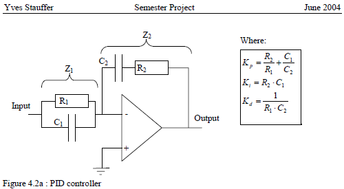
[13:18:58] <z64555> https://www.gully.org/~mackys/lj/opamp-pid.png
[13:19:20] <z64555> It's been awhile since I messed with one, but that should be a PID circuit
[13:20:09] <z64555> What happens to a capacitor/resistor tank circuit when the supply voltage is shut off?
[13:20:41] <z64555> It smoothly decays
[13:20:45] <vaskozl> Ok
[13:21:26] <z64555> You can simulate the line by unit step or rectangular wave forms
[13:21:43] <z64555> and then you can test it with like a ramp waveform
[13:21:56] <z64555> and maybe finally with a sinewave
[13:22:33] <z64555> Or you could just tweat the R values until it works :P
[13:22:36] <z64555> *tweak
[13:23:39] <vaskozl> I see
[13:23:49] <vaskozl> Now I have a microcontroller
[13:23:59] <vaskozl> and I'm not sure I want to use op amps
[13:24:14] <z64555> that's cool. If you have a uC you can make the calculations in it
[13:24:29] <z64555> and skip the use of the op amps
[13:24:48] <vaskozl> I mean I do have op amps I can use, but I'm not sure if it would be better.
[13:24:52] <vaskozl> what is uC?
[13:25:10] <z64555> u (micro) C(ontroller)
[13:25:17] <vaskozl> oh
[13:25:32] <z64555> I use u instead of mu, because that requires an alt-code on the keyboard :P
[13:25:48] <vaskozl> fair enough
[13:26:04] <z64555> µ
[13:26:08] <vaskozl> Would you mind explaining a bit more about the alogirithm behind pid?
[13:26:19] <vaskozl> so do I need analogue value from the sensor?
[13:26:35] <vaskozl> or would a boolean value work for pid as well?
[13:27:00] <z64555> Well, you can either have 2 PID's that control each motor side individually, or 1 PID that controls both
[13:28:25] <z64555> The two PID's cost more computationally, but allow you some wiggle room if your bot tends to list to one side, or for whatever reason has a different turning rate
[13:28:53] <z64555> the 1 PID system would require a translation block between like, -1 and 1
[13:29:01] <z64555> with 0 as center
[13:29:41] <vaskozl> -1, 0 and 1 sounds good
[13:29:43] <z64555> bools won't work for pid, must be ints or floats
[13:30:11] <vaskozl> wouldn't it be only 3 values then?
[13:30:14] <z64555> (well, it will work, but that's crossing the digital with analog streams)
[13:31:07] <z64555> That's up to you. You could try the tri-state input for now, and maybe go into something more analog later on
[13:31:13] <vaskozl> so if -1 means we have the left sensor of the line and +1 we have the right sensor of the line (0 both on), how would we proceed?
[13:31:50] <vaskozl> s/of/off/g
[13:32:15] <z64555> mkay...
[13:32:34] <z64555> The P gain is multiplied to the input directly
[13:32:43] <z64555> I is an accumulator
[13:32:56] <z64555> and D is the difference between this sample and last sample
[13:33:08] <z64555> https://en.wikipedia.org/wiki/PID_controller
[13:34:20] <z64555> The I and D terms both have a gain factor applied to them
[13:34:27] <z64555> which scales up or down their affect
[13:35:11] <vaskozl> Ok I can do that.
[13:35:20] <vaskozl> Thanks
[13:35:27] <z64555> If you want the mathmatical formula of a PID in discrete time, just take the z-transform of u(t) on that wiki
[13:35:38] <z64555> You're welcome. :)
[13:37:32] <z64555> Be sure to read that section on Loop tuning, in particular stability
[14:18:09] <vaskozl> z64555: my pid code works :)
[14:18:21] <vaskozl> I also found out I can make my motors beep
[14:18:31] <myself> they're transducers!
[16:39:16] <z64555> Yeah, if you send an audible waveform to your motors, you can make em beep like a speaker
[16:39:42] <z64555> also congrats! :)
[16:51:43] <z64555> vaskozl: your next challenge, should you accept it, is to make a fuzzy logic controller. :)
[18:43:40] <anonnumberanon> <vaskozl> Now I'm looking to optimise the alogirithm.
[18:43:43] <anonnumberanon> show code
[19:29:46] <vaskozl> anonnumberanon:
https://github.com/Vaskozl/EEbug/blob/master/main.c
[19:30:54] <vaskozl> I'm still really new to programming microcontrollers, and am only just figuring things out.
[20:14:27] <MarkX> hi
[20:15:34] <MarkX> any tips on where i can read about or see some sample code for dc position control using a discreet trapezoidal profile with PWM?
[20:26:06] <rue_shop3> you want a discrete pwm gen, for making a position servo?
[20:26:21] <rue_shop3> I have some circuits
[20:26:32] <rue_shop3> what freq. pwm? 300Hz for motors?
[20:31:49] <MarkX> rue_shop3: yes discrete pwm gen. basically i have a dc motor connected to a potentiometer using an elastic band
[20:32:35] <rue_shop3> sure
[20:32:51] <rue_shop3> do you have an oscilloscope?
[20:32:52] <MarkX> the freq for the pwm... not gonna lie, i don't remember
[20:33:01] <MarkX> let me check my code for the atmega32u4 that i'm using
[20:33:05] <MarkX> no i do not :(
[20:33:05] <rue_shop3> 300Hz is good for mtoors
[20:33:26] <rue_shop3> ok, well
[20:33:41] <rue_shop3> I wonder whats harder to adjust, my new version or a regular one
[20:33:55] <rue_shop3> do you have any analog chips to make this from?
[20:34:15] <rue_shop3> LM393
[20:34:46] <rue_shop3> ?
[20:34:49] <MarkX> i currently have an atmega32u4 connected to some motor driving ics. i can get basic pwm out to get the motor to move
[20:34:59] <rue_shop3> yea, you want to go discrete
[20:35:24] <MarkX> hmm maybe i am misunderstanding what discrete is
[20:36:06] <MarkX> Trapezoidal profile mathematics
[20:36:07] <MarkX> The basic math required to execute trapezoidal profiles is straight- forward. There are two forms that can be used; the continuous form (from high school physics) and the discrete-time form found in most motion systems (systems using microprocessors or DSPs to generate new motion parameters with each tick of the motion clock).
[20:36:13] <MarkX> omg sorry, horrible paste
[20:37:00] <rue_shop3> yea basically what you want is to make a triangle wave and use a compaitor against it and a control voltage
[20:37:05] <rue_shop3> the result is a pwm wave
[20:37:17] <rue_shop3> I use a scope to adjust all mine
[20:37:28] <MarkX> isn't that what the timer/pwm does already?
[20:38:04] <MarkX> i thought i'd be able to just give my PWM a value between 0 and 255 after some math
[20:38:04] <rue_shop3> did you want to use the microcontroller to generate the pwm or make it discretely?
[20:38:19] <MarkX> microcontroller pwm generation is fine
[20:38:28] <MarkX> it already works and works well, no point in reinventing the wheel
[20:38:33] <MarkX> sorry if i used the wrong word/phrasing
[20:40:00] <rue_shop3> sorry I got 3 things going and I cant work out what you want
[20:40:08] <rue_shop3> keep trying to describe
[20:42:05] <MarkX> okay so i have the motor, it's connected to a potentiometer using a rubber band. i want to make the motor move from position A to position B. exact position can be measured using the pot. i currently have a PWM signal going to the motor, i also have an ADC value for the pot's current position
[20:42:43] <MarkX> i want a function basically where i do "moveTo(motorNumber, positionToGoTo)"
[20:44:33] <MarkX> i was hoping to use a trapezoidal profile which takes in my input from the potentiometer and outputs a number between 0 and 255 which i assign to my PWM
[22:06:37] <robotustra> hi
[22:08:16] <MarkX> hello
[22:13:13] <mrdata-> hola
[22:13:41] <robotustra> how is everything?
[22:13:59] <MarkX> would either of you guys know about trapezoidal profiles?
[22:14:04] <MarkX> specifically for motor position control
[22:14:20] <robotustra> give a picture
[22:14:59] <MarkX> hmm?
[22:15:28] <robotustra> of profile
[22:29:49] <anonnumberanon> jhylands, what oven do I need again for smd?
[22:30:41] <anonnumberanon> i gotta buy one to cure a freshly painted pipe, thought of doing that so that i could use the oven later for reflow. It needed to have just a rotating knob on the front?
[22:30:44] <Tom_itx> anonnumberanon, a toaster oven will do just fine
http://tom-itx.no-ip.biz:81/~webpage/toaster_oven/toaster_oven_index.php
[22:32:42] <anonnumberanon> Tom_itx, thanks dude
[22:32:50] <anonnumberanon> ill go get one tomorrow morning
[22:33:43] <Tom_itx> 4 element is better than 2
[22:40:39] <z64555> trapezoid profile...
[22:40:48] <z64555> MarkX: that sounds suspiciously fuzzy
[22:41:09] * z64555 googles
[22:44:51] <z64555> yeah, this is new to me
[23:01:57] <MarkX> sorry
[23:01:59] <MarkX> i got called away
[23:02:23] <MarkX> robotustra: basically this
[23:02:24] <MarkX> http://machinedesign.com/motion-control/mastering-motion-profiles
[23:02:49] <MarkX> i was hoping to find a good code reference or a tutorial for it