Back
[01:43:15] <witnit> yeah but no sense in fixxing such things if the machine has bad latency I think is why jdh was asking him such things.
[02:11:49] <Deejay> moin
[02:52:38] <MrSunshine> hmm looks like 0x80808080 also is right, as it seems it doesnt care what value i3 and i4 has with that ocnfiguraion .. can be 0, and be 1 . .its still true to the statement (i0 & i1 & i2)
[03:25:29] <archivist_herron> CaptHindsight,
http://www.bbc.co.uk/news/technology-27243376
[03:40:05] <MrSunshine> gaah i would like to reporgram this pendant to use the A axis to set tool diameter fňr the /2 button on the pendant =)
[03:40:33] <MrSunshine> just put it in A mode and dial in the current tool diameter ... but sounds like alot of work :/
[03:53:57] <MrSunshine> nah i think its to much hassle .. i will just have to know the diameter and move myself in or out before zeroing out to get the actual cutter zero
[04:58:34] <Loetmichel> *ha* got it working! ->
http://www.cyrom.org/palbum/main.php?g2_itemId=14877
[05:01:34] <Loetmichel> ... only had to make the lid 2 times to fit the bottom ;-)
[05:27:50] <MrSunshine> oh sex on a stick!
[05:27:57] <MrSunshine> nice =)
[06:20:58] <Loetmichel> MrHindsight:hmm?
[06:21:02] <Loetmichel> MrSunshine
[08:54:32] <MrSunshine> LeelooMinai, i think its something dave in eevblog usaly says when its something almost pornographic :P
[08:55:12] <MrSunshine> hmm lut5 does not want to be named
[08:55:13] <MrSunshine> :/
[08:55:35] <MrSunshine> linuxcnc "crashes" when i try to do "loadrt lut5 names=somehing"
[09:29:02] <jdh> so, I'm thinking about paying $200 for teh super custom bike fit
[09:29:04] <jdh> <urk>
[09:35:54] <pcw_home> MrSunshine" someone on the forum had similar troubles with named lut5s (no crash but some sort of bug like variable overlap)
[09:39:27] <jthornton> MrSunshine,
http://wiki.linuxcnc.org/cgi-bin/wiki.pl?Lut5
[09:39:36] <jthornton> additional info and calculator
[09:48:30] <cradek> MrSunshine: can you give me more details? I'm not getting a crash when I try that in 2.5 branch/sim
[09:49:31] <Jymmm> http://linuxcnc.org/docs/html/man/man9/lut5.9.html
[09:52:04] <Jymmm> I'm not sure what WEIGHT is meant there, but okey.
[09:53:07] <jdh> I have some extra if you need it.
[09:54:30] <Jymmm> heh, that's okey... You can save that for when/if you get a boob/butt job "Does this injected fat make my boobs looks big?"
[09:56:32] <Jymmm> jdh: If you have extra, maybe you need to stop using that scooter so much ;)
[09:57:37] <Jymmm> jdh: swi/dive the old fashion way, using your arms and legs =)
[10:00:55] <CaptHindsight> archivist: thanks for the link, I'll have to look at the waxes again. They must have found a wax that has a fast enough phase change.
[10:04:28] <jdh> no arms involved in diving. I do swim a lot. Even scootering, I will scooter back 4,000ft, then swim.
[10:06:29] <Jymmm> jdh: You can't use your arms diving?
[10:11:02] <jdh> it is very inefficient and not needed.
[10:11:33] <jdh> anyone using arms is someone I would avoid.
[10:12:06] <Jymmm> heh
[10:13:12] <_methods> http://arstechnica.com/tech-policy/2014/05/web-host-gives-fcc-a-28-8kbps-slow-lane-in-net-neutrality-protest/
[10:16:02] <Jymmm> heh
[10:16:32] <CaptHindsight> love it
[10:16:58] <_methods> wish some of the big boys would do the same thing
[10:17:16] <_methods> throttle all .gov sites
[10:17:27] <CaptHindsight> whats often gotten the point across to someone in government is subjecting them to their own rules
[10:17:37] <_methods> yep
[10:17:45] <_methods> throttle all their ips
[10:18:06] <_methods> see what happens when capitol hill can't get streaming porn
[10:19:11] <jdh> I believe that is covered under the 8th amendment.
[10:20:35] <_methods> hehe
[10:23:14] <Loetmichel> archivist: seen the result of the drawing from yesterday?
[10:23:17] <Loetmichel> [11:40] <Loetmichel> *ha* got it working! ->
http://www.cyrom.org/palbum/main.php?g2_itemId=14877
[10:23:17] <Loetmichel> [11:43] <Loetmichel> ... only had to make the lid 2 times to fit the bottom ;-)
[10:24:18] <jdh> do you have to debur much after cutting those?
[10:24:22] <Jymmm> http://arstechnica.com/tech-policy/2014/05/surveillance-camera-clears-woman-hit-by-police-car/
[10:24:37] <Loetmichel> just a quick "go round" with a deburring tool
[10:24:43] <Loetmichel> had deburring tool
[10:25:06] <Loetmichel> and when the mill bit hadnt cut 2kg of aluminium : not even that ;-)
[10:25:11] <Loetmichel> hand
[10:33:56] <tjtr33> CaptHindsight, you shoulda worked with Douglas Adams
http://imagebin.org/309878
[10:37:21] <CaptHindsight> :)
[10:41:25] <CaptHindsight> archivist: that display can be made for less than the cost of an LCD display
[10:45:44] <Deejay> LC display or LCD
[10:45:45] <SpeedEvil> CaptHindsight: really, really debatable.
[10:45:48] <CaptHindsight> their £1.2m grant has run out!? what were they doing spending it on parties?
[10:45:57] <SpeedEvil> CaptHindsight: It also has onerous power requirements likely
[10:46:44] <CaptHindsight> I just ran the numbers, power is not an issue
[10:47:27] <SpeedEvil> Using what data?
[10:48:04] <SpeedEvil> Also - 7" LCDs are well under $20 in bulk
[10:48:14] <pcw_home> those electrostatically driven elastomers would be lower power (assuming you could get enough motion)
[10:48:26] <CaptHindsight> Joules/per dot ate required height
[10:49:07] <CaptHindsight> it's not electrostatically driven, it phase change wax
[10:49:16] <CaptHindsight> ate/at
[10:49:34] <pcw_home> I'm not talking about the wax one
[10:49:50] <CaptHindsight> yeah, I can make a wax based display for a few $$
[10:50:33] <CaptHindsight> PCW: sorry yeah, ends up the EAP's are ~100V/um of travel
[10:51:47] <CaptHindsight> i was trying to use EAP's but they either require too high a working voltage 4-5KV or a cantilever
[10:54:53] <CaptHindsight> the wax display is mainly a pcb with a silicone film with conductive wax cells and a frame for the dot channels to expand and contract into
[10:57:15] <pcw_home> similar wax as car thermostat wax?
[10:57:44] <CaptHindsight> paraffins
[10:58:34] <CaptHindsight> you can tweak their structure to modify the phase change
[10:59:46] <pcw_home> anyone who has cast candles knows how much paraffin shrinks
[11:01:17] <CaptHindsight> if the wax is also the heater then the pcb is even easier to make
[11:03:01] <CaptHindsight> the wax is actually a bot slow to transition but if make a large display it doesn't have to refresh as often
[11:03:08] <CaptHindsight> bot/bit
[11:04:07] <CaptHindsight> I wonder how many patents cover the design?
[11:05:17] <pcw_home> give up on the fishing line version?
[11:06:06] <CaptHindsight> too many moving parts for my liking, but it will work
[11:06:22] <pcw_home> seems like for that you just want a standard component (tall and skinny) that mounts to a PCB
[11:06:57] <CaptHindsight> like a Pogo pin
[11:07:05] <pcw_home> yeah
[11:07:39] <CaptHindsight> I worked out a low cost system using pogo pins and latches that is manually triggered or rest
[11:07:53] <CaptHindsight> rest/reset
[11:08:50] <CaptHindsight> but too many moving parts, small levers, latches, pogo pins etc
[11:08:53] <Connor> CaptHindsight: Am I reading correctly.. a display screen made of wax ?
[11:09:16] <pcw_home> but a pogo pin with heater/nylon/spring/connections
[11:09:19] <CaptHindsight> was based actuator for Braille
[11:09:36] <CaptHindsight> Connor: ^
[11:16:19] <CaptHindsight> http://www.caltherm.com/_images/products/diaphragm-actuator-design.jpg same principle
[11:17:33] <CaptHindsight> http://www.youtube.com/watch?v=SmuDltaKPQQ
[11:20:53] <CaptHindsight> what would make it even more efficient is a thermal gate/switch to act as an insulator or thermal conductor that can be switched on and off
[11:43:24] <CaptHindsight> http://www.google.com/patents/US5709740 figures, almost expired
[11:47:34] <CaptHindsight> http://www.google.nl/patents/WO1997015630A1?cl=en
[11:47:58] <tjtr33> CANduino is _not_ an Arduino Controller Area Network implementation
https://labitat.dk/wiki/CANduino (do Danes really call it a 'can'? )
[11:48:51] <CaptHindsight> it's anything goes Friday
[12:12:47] <PetefromTn_> Afternoon folks..
[12:13:07] <PetefromTn_> How is everybody in the LinuxCNC world today LOL?
[12:14:58] <tjtr33> Hi Pete
[12:15:08] <tjtr33> a buddy wants to use reprap to make quik&dirty models of car parts before using cnc to cut metal.
[12:15:17] <tjtr33> is it practical in time & materials to ( for instance) model a caliper mount to really see interference as we turn the wheels?
[12:15:19] <tjtr33> is this a reasonable use for reprap?
[12:15:37] <CaptHindsight> it's cheaper to make a DLP resin printer
[12:15:42] <CaptHindsight> they are also faster
[12:16:02] <tjtr33> really? i thought DLP printing was still scifi
[12:16:13] <tjtr33> any links to projects?
[12:16:37] <tjtr33> yah yah i can google it, thx for the tip
[12:17:03] <CaptHindsight> https://code.google.com/p/lemoncurry/wiki/main but go top down projection
[12:17:32] <CaptHindsight> the projector and vat are stationary only the stage moves
[12:18:21] <tjtr33> ok might use my epson and sable 2015 hacked up :)
[12:18:43] <CaptHindsight> the z-axis with stage is the only moving part
[12:18:50] <tjtr33> is it really a single axis? just Zposn++ ?
[12:18:52] <tjtr33> wow
[12:19:09] <CaptHindsight> you dunk the stage under the resin and lift it to the desired layer thickness
[12:19:20] <CaptHindsight> expose, dunk, repeat
[12:19:47] <tjtr33> oh Zposn-- :)
[12:20:14] <tjtr33> will read up thx
[12:20:26] <CaptHindsight> http://www.youtube.com/watch?v=eKk2vRysioE starts around 1:00, but use a projector vs laser and galvo
[12:21:43] <CaptHindsight> the distance between the surface of the resin and the last cured layer below sets the layer thickness
[12:21:52] * SpeedEvil wonders about e-beam selective sintering.
[12:21:58] <CaptHindsight> it works
[12:22:24] <CaptHindsight> same for e-beam deposition
[12:23:01] <CaptHindsight> most of this stuff is 10-20 years old but has been suppressed by the patent holders
[12:23:14] <CaptHindsight> if they can't have their way then nobody wins
[12:23:38] <tjtr33> oh upside down from my 1st mental image, stalactites
[12:23:45] <SpeedEvil> Oh - I know in principle it works.
[12:23:52] <SpeedEvil> I was wondering on my vacuum pump.
[12:23:57] <CaptHindsight> tjtr33: don't go with the bottom up projection
[12:24:05] <CaptHindsight> too complicated
[12:24:31] <tjtr33> " but go top down projection" ok
[12:24:41] <CaptHindsight> the bottom up uses a clear vat that you project the light onto from underneath
[12:25:21] <SpeedEvil> how does the stuff not stick to the base?
[12:25:27] <CaptHindsight> the issues are separating the cured part from the vat after each layer is cured
[12:25:43] <CaptHindsight> if you use top down it's not an issue
[12:26:07] <CaptHindsight> if you use bottom up then the resin acts like an adhesive
[12:27:05] <CaptHindsight> even if there was no adhesion there is still a pressure differential so it acts like a suction cup
[12:27:49] <CaptHindsight> there are some tricks to the materials used for the clear vat bottom and how it gets separated
[12:28:27] <tjtr33> are the parts delicate? could i hold it in place to see fit & interference w/o having it crumble?
[12:28:32] <CaptHindsight> PTFE or high oxygen containing films plus tilting for example
[12:28:54] <tjtr33> i dont expect to bolt it up
[12:29:04] <CaptHindsight> tjtr33: I'm making parts that you can hit with a bat
[12:29:16] <tjtr33> this sound good
[12:29:18] <SpeedEvil> tjtr33: 3d printed stuff is generally as strong as most other non-structural plastic
[12:29:27] <SpeedEvil> Think your average toy
[12:29:41] <CaptHindsight> tjtr33: I can hook you up with the resins/photopolymers
[12:29:46] <SpeedEvil> If it's a thick section, it can be quite strong indeed
[12:29:53] <SpeedEvil> Even with PLA
[12:30:04] <tjtr33> hmmm charles prints of venus were a bit fragile ( wichita )
[12:30:20] <SpeedEvil> It depends on the material
[12:30:31] <SpeedEvil> you get everything from sand to inconel.
[12:30:40] <SpeedEvil> Inconel isn't noticably weak :)
[12:30:44] <CaptHindsight> I'm blending metal resin composites that have qualities similar to 6061
[12:31:02] <tjtr33> Capt thx, will see if my epson is strong enuf for a DLP
[12:31:18] <tjtr33> SpeedEvil, what about your vacuum?
[12:31:45] <CaptHindsight> yeah no problem, I even blend for sensitivity into the Blue 470nm
[12:32:18] <SpeedEvil> tjtr33: I have a vacuum pump that's basically adequate to evacuate a chamber well enough for e-beam sintering
[12:32:22] <CaptHindsight> tjtr33: you can use the epson as is, it might even be an LCD vs DLP
[12:32:32] <SpeedEvil> CaptHindsight: err - metal composites light set?
[12:33:22] <CaptHindsight> SpeedEvil: yeah, metals, ceramics, carbon fiber, CNT's etc etc
[12:33:46] <SpeedEvil> Nontransparent composite seems to have issues :)
[12:34:08] <SpeedEvil> Unless you're using a transparent matrix and sufficiently low fill fraction/depth that it can get round the edges by internal refraction
[12:35:11] <SpeedEvil> Saw a rather insane method to grow nanotubes on CF
[12:36:11] <CaptHindsight> http://www.3ders.org/articles/20140415-ecn-uses-new-dlp-technology-for-3d-printing-metals.html
[12:36:22] <CaptHindsight> it's not new
[12:36:31] <SpeedEvil> https://connect.arc.nasa.gov/p7qyuvlzby8/
[12:37:04] <SpeedEvil> - Take CF cloth, rinse in acetone to remove sizing, dry, dip in ferrocene, dry, microwave for 45 seconds
[12:37:31] <SpeedEvil> you get nanotubes at right angles to the CF fibres
[12:37:34] <IchGuckLive> hi all
[12:37:55] <CaptHindsight> man that site took forever to load
[12:39:03] <SpeedEvil> err - wrong link
[12:40:02] <CaptHindsight> slurry impregnated CMC is also interesting
[12:40:44] <SpeedEvil> indeed
[12:41:03] <SpeedEvil> http://nari.arc.nasa.gov/seedling2014 - a hell of a lot of interesting stuff in the LEARN program
[12:41:43] <CaptHindsight> new piezo fuel injectors arrived yesterday, time to make some mods
[12:41:55] <tjtr33> Panasonic EMP-1705 is TFT active matrix XGA 1024x768x3, 170W UHE bulb
[12:42:26] <SpeedEvil> http://nari.arc.nasa.gov/learnseminar2013 - it was the 'poptube' link
[12:42:33] <tjtr33> CaptHindsight, maybe i can help modding the nozzles ( my edm has 4 axis now but generator stilld ead )
[12:46:43] <CaptHindsight> tjtr33: do you have one of the micro graphite cantilever tips?
[12:47:35] <CaptHindsight> oh that's another project we talked about last year since we can fabricate sub-micron graphite tips
[12:50:10] <tjtr33> i grind subgate electrodes for mold runner systems, the tip itself passes thru the part, so it's pointyness is usually unimportant ( and has 0 dia theoretically )
[12:51:09] <tjtr33> sometimes graphite is not the material to use , maybe copper tungsten ( use it slower but many more times )
[12:51:24] <tjtr33> lemmeno
[12:53:00] <tjtr33> i've done openings .001 on long axis and .0008 on short axis ( cone intersect plane )
[13:00:42] <CaptHindsight> tjtr33: whatever you do don't remove the color wheel if its a DLP, too much risk and not needed
[13:05:33] <tjtr33> i think its 3 layers TFT from the '1024x768x3' description,
[13:05:33] <tjtr33> i think 170W UHE bulb just shines thru it to the optics, but i havent cracked the case
[13:09:22] <tjtr33> http://www.projectorcentral.com/Epson-EMP-1705.htm 1700 lumens 'Display: Type: 0.7" 3 LCD'
[13:09:42] <tjtr33> a school downstate sold off a pile of 'em cheap
[13:13:18] <MrSunshine> cradek, nah sorry, dont know what version of emc im on on the cnc computer but i dit "loadrt lut5 names=all_homed" and getting a crash of some kind about "named"
[13:13:59] <MrSunshine> jthornton, yeah found the calculator yesterday =) been using it =) great to be able to write in understandable way =)
[13:14:36] <CaptHindsight> tjtr33: that will work, don't open it
[13:16:06] <MrSunshine> cradek, i can check version etc tomorrow =)
[13:16:27] <tjtr33> CaptHindsight, :) good advise, and easy enuf for me to follow light goes thru 3 'scrims'
http://www.3lcd.com/explore/
[13:16:51] <MrSunshine> (the crash i call it is that i get a debug window from linuxcnc .. i guess i could copy that also if i can reproduce the problem tomorrow =)
[13:17:03] <CaptHindsight> you'll just be using the Blue and maybe the RED for alignment and focus
[13:17:14] <CaptHindsight> the RED doesn't trigger polymerization
[13:17:53] <MrSunshine> got the =0 button working today so it cannot try and call mdi command when one axis is not homed atleast! =)
[13:17:54] <CaptHindsight> so you can display alignment patterns with Red and then polymerize with Blue
[13:18:01] <MrSunshine> all by myself .. with some help from my friends ;P
[13:21:29] <tjtr33> CaptHindsight, red for fiducial marks, cool, now i imagine something _like_ Slic3r being told to output blue only [lots to read up on]
[13:23:07] <CaptHindsight> or white, anything so you get 100% blue
[13:24:16] <CaptHindsight> http://imagebin.org/309915 injector nozzles
[13:26:05] <IchGuckLive> Loetmichel: flashligt has arrived after 28 days
[13:26:35] <CaptHindsight> http://imagebin.org/309916 so around ~100um dia stock
[13:26:51] <CaptHindsight> nice round holes!
[13:27:58] <tjtr33> CaptHindsight, round at .004" usually requires a rotobare ( tm) but depth to dia ratio is the problem, so how deep?
[13:28:12] <tjtr33> Rotobore
[13:30:03] <CaptHindsight> depends on material and pressure, these piezo units can deliver 2000 bar, that would allow you to inject right though skin nearly into bone
[13:31:38] <CaptHindsight> I just need to move nanogram-picogram drops at 10m/sec
[13:31:50] <tjtr33> i meant how thick is the plate that the hole passes thru
[13:32:55] <CaptHindsight> haven't decided yet, depends on if I make a whole nozzle tip like the factory or mod these and just make a new tip
[13:33:39] <CaptHindsight> for inkjet 25um holes a 25-50um SS plate is enough
[13:35:09] <CaptHindsight> it should be at least a few hundred micron thick to give them durability or it's like trying to keep a foil from getting damaged
[13:35:36] <tjtr33> oh good, cuz 100x dia to depth is crazy hard to do, you're talking 1:1 worst case, DIY ECM may do it ( salt water & a dc supply )
[13:36:53] <CaptHindsight> oh, thats just the low/small end of things, I'll also have 100-200um holes in 200um SS
[13:37:43] <CaptHindsight> I can also print nozzles with 25um holes
[13:38:35] <CaptHindsight> another option is 25um holes in 25um foil and then stack them 10-20x
[13:51:26] <PetefromTn_> Woo Hoo...UPS man just dropped off a package!! LOL
[13:54:28] <PetefromTn_> Awesome just got my brand new Kurt vise...It even SMELLS accurate LOL
[13:56:01] <CaptHindsight> will you be posting vise pron pics next? :)
[14:00:16] <PetefromTn_> Do you need some LOL I can help ya out there man...
[14:00:33] <Tom_itx> 6 or 8" ?
[14:00:47] <PetefromTn_> 6" D 688
[14:00:55] <Tom_itx> standard issue
[14:01:03] <PetefromTn_> yup
[14:01:04] <CaptHindsight> how much was the shipping? whats the weight ~80lbs?
[14:01:13] <PetefromTn_> The goto vise for machine shops..
[14:01:40] <PetefromTn_> I got the vise brand new shipped to my door for $504.00
[14:05:20] <PetefromTn_> I like this little sheet plate that keeps chips out of the screw it comes with.
[14:18:34] <MrSunshine> hmm now im in a bit of a dilema :P
[14:19:01] <MrSunshine> ive edited my configs etc sň much so i cannot run step config anymore ... and i need to add a Z home and limit switch .. but only for one direction of limit
[14:19:26] <MrSunshine> http://wiki.linuxcnc.org/cgi-bin/wiki.pl?Homing_And_Limit_Switch
[14:19:26] <MrSunshine> ahh
[14:22:37] <CaptHindsight> http://www.kurtworkholding.com/manual-vise-opening-p-2884-l-en.html $469.60 USD SCRATCH AND DENT
[14:25:42] <tjtr33> i got a schmidt but grinding vises are different beasts
https://www.hschmidt.com/productcart/pc/Precision-Grinding-Vise-4-Capacity-VO-4-15p213.htm
[14:35:48] <CaptHindsight> http://www3.menards.com/main/tools-hardware/power-tools/drill-presses/4-drill-press-vise/p-1682503-c-10086.htm so you're saying that I got ripped off for $40 when I got this instead?
[14:44:16] <tjtr33> heh not if you're a carpenter or plumber
[14:44:46] <tjtr33> great trades, no offense, but a different scale fer sure
[14:49:44] <Connor> PetefromTn_: You didn't get a CNC style vise ?
[15:24:30] <deMimsy> How would one get g-code parameter values using python commnands?
[15:41:26] <tom_83> Hi
[15:42:05] <tom_83> I'm trying to write my first G code program, and my brain hurts
[15:42:33] <tom_83> If T1 is a 6mm end mill and I do this:
[15:42:37] <tom_83> G21
[15:42:39] <tom_83> G40
[15:42:45] <tom_83> T1M6
[15:42:52] <tom_83> G1 X30 F500
[15:43:05] <tom_83> G42 G1 X0 F500
[15:43:19] <tom_83> then what will me DRO read?
[15:43:32] <tom_83> (assuming is read 0,0,0 before I started
[15:45:17] <_methods> x0 i guess your program is kinda.......whack
[15:45:33] <_methods> probably will error out on that comp move
[15:46:14] <CaptHindsight> tjtr33: I have to redesign these for my applications
http://imagebin.org/309935 down the nozzel where the pintle sits,
http://imagebin.org/309936
[15:46:33] <_methods> but i guess if you have nothing in comp for the tool it will just ignore it
[15:46:43] <tom_83> it reads X1.243 Y3
[15:47:03] <_methods> is there a value in comp for that tool?
[15:47:08] <tom_83> just a sec
[15:47:35] <tom_83> the only thing in the tool table is X and dia
[15:47:40] <tom_83> sorry, Z and dia
[15:47:42] <_methods> and by DRO do you mean the axis DRO screen or do you mean a separate dro attahced to it
[15:48:02] <tom_83> yeah Axis DRO, i'm just playing with the sim
[15:48:12] <_methods> what is dia in comp page?
[15:48:19] <_methods> 2.286?
[15:50:12] <tom_83> ... what's the comp page?
[15:53:03] <tom_83> it just uses the data from the tool table doesn't it?
[15:53:34] <tom_83> dia in the tool table for tool No.1 is 6mm
[15:58:20] <CaptHindsight> pintle tip, this is what blocks the orifices while the valve is closed
http://imagebin.org/309940
[16:00:51] <CaptHindsight> 2mm diameter tip with ~170um orifices
[16:02:15] <tjtr33> gotch ( could not get this for that photo tho )
http://www.dieselmotors.info/wp-content/uploads/2011/02/pintle-nozzles.jpg
[16:03:01] <tjtr33> so are these things spring loaded and solenoid retrcated?
[16:03:11] <CaptHindsight> only injector tip squirt sideways and all over the place :)
[16:03:22] <CaptHindsight> yeah, this one is
[16:03:57] <CaptHindsight> some use a hydraulic pressure amplifiers
[16:05:20] <CaptHindsight> the aftermarket nozzles claim to be done by edm
[16:07:40] <tjtr33> a lot of tiny edm done in southern California, orifices, bonding tools, really teensy stuff you need microscopes to see
[16:07:53] <tjtr33> waveguides too
[16:10:49] <CaptHindsight> for the larger orifices >0.2mm just drilling
[16:13:30] <CaptHindsight> http://www.najet.com/micro-hole-drilling/?gclid=CPj1z4Ldn74CFedFMgodaEwA5Q
[16:14:00] <tjtr33> national jet is good but for no burrs they'd edm
[16:16:13] <CaptHindsight> http://www.ebay.com/itm/like/151226995229?lpid=82 these fit in my old B&D cordless :)
[16:16:31] <tjtr33> i think it was the owner, who once at IMTS saw a 'tiniest edm electrode' proported, took it home, edm'd a hole thru it, then returned it with the smaller electrode tied in a knot thru the hole
[16:16:56] <CaptHindsight> nice
[16:18:51] <tjtr33> heh the chuck runout would be > dia, .006"dia would need a perfect setup
[16:19:21] <CaptHindsight> heh
[16:20:01] <CaptHindsight> now you know why I've been working with all these piezo and linear motors
[16:21:09] <tjtr33> tom_83, for me it runs ok. i used inch tooltable with .23622 dia, and end posn was X0 Y.1181 ( with G42D1 and with G41 [no D ] )
[16:21:23] <tjtr33> isnt that correct? 1/2 dia offset to right?
[16:21:54] <tjtr33> Capt any inchworm feed units?
[16:22:01] <tjtr33> CaptHindsight, ^^
[16:22:28] <CaptHindsight> most of this is just temporary steps to build the real tools, printheads to print printheads, machines to make smaller machines
[16:22:45] <tjtr33> like ultra precision drafting pencil advancers
[16:22:59] <tjtr33> ooh you into real govt work then
[16:23:17] <CaptHindsight> yeah, piezo and EAP (electro active polymer)
[16:23:29] <Deejay> gn8
[16:23:41] <CaptHindsight> shhh
[16:24:59] <CaptHindsight> we need machines small enough to work with nerve endings, print blood vessels, make small valves etc etc
[16:25:35] <tjtr33> borg me!
[16:25:53] <CaptHindsight> http://www.3ders.org/articles/20140508-china-using-3d-bio-printer-to-create-artificial-dura-mater.html
[16:26:11] <CaptHindsight> http://www.3ders.org/articles/20140509-3d-printed-hydrogel-nanocomposites-helps-to-detoxify-the-blood-like-a-liver.html
[16:27:16] <CaptHindsight> soon enough
[16:28:43] <tjtr33> grinders & biohackers ( diy borgz)
[16:30:24] <tjtr33> http://collaborate.biohack.me/Grinder_Resource_Library
[16:30:49] <CaptHindsight> with the way healthcare has been turned into a business it looks like everyone is going to be going to China for replacement parts, like that eye shop in Blade Runner
[16:31:04] <tjtr33> what is the material used to print new dura layers? harvested or grown?
[16:31:30] <tjtr33> argh horror stories of HongKong shopper missing,t hen turning up sans liver
[16:32:00] <tjtr33> "no no no i only do eye"
[16:32:21] <tjtr33> " you nexus right?"
[16:32:36] <CaptHindsight> that article uses synthetic materials
[16:33:04] <tjtr33> i thought its be real organic, wow, even more scifi
[16:34:01] <CaptHindsight> now i see why all the stem cell research was put on hold here in the 00's
[16:34:33] <CaptHindsight> less money in cures vs treating symptoms
[16:35:24] <tjtr33> true, very chinese to look at cause, very western to cut it off or make it feel better
[16:35:55] <tjtr33> chinese/eastern
[16:35:58] <CaptHindsight> combining EDM with DMLS might be a good approach for small precision metal parts
[16:36:20] <tjtr33> ? (googles DMLS)
[16:36:31] <CaptHindsight> direct metal laser sintering
[16:39:48] <CaptHindsight> EDM in nitrogen atmosphere
[16:40:01] <tjtr33> found it, some very nice tiny parts, so get net shape up with laser welding the power and refine with edm ( needs multiaxis edm and primitive shape tools [cyl sphere rect prisms... ])
[16:40:12] <CaptHindsight> you got it
[16:40:28] <tjtr33> oh dry EDM, up in Mich at uni
[16:40:52] <CaptHindsight> then they could share the same atmosphere
[16:41:20] <tjtr33> way too interesting, i gotta go exercise... walkies! bbl
[16:42:49] <tom_83> tjtr33, the DRO shows you the centre axis of the spindle
[16:43:28] <tom_83> and a had more moves that that in my program, so I think it was stopping short ready for the net move?
[16:43:46] <tom_83> i'm sort of getting the hang of it
[16:48:59] <tjtr33> yeah so the center of the tool is 1/2 dia away from the line. that seems ok to me, you got 1/2 cutter dia offset applied at that point.
[16:49:12] <tjtr33> what did you expect to have happen? or see?
[16:50:47] <tjtr33> sorry to reply & run, but bbl
[16:51:02] <tom_83> when I ran it, it was stopping short of X0 because I had more lines in my program...
[16:51:24] <tom_83> when I tool the following lines out (and just ran what I typed in here) I did as I expected
[16:51:43] <tom_83> it's my first go, much to learn
[16:52:04] <tom_83> took the following lines out*
[17:10:50] <zeehero> Are these any equivalent open source arduino shields like RAMPs (for Repraps) for diy cnc mills?
[17:10:56] <zeehero> are there*
[17:17:30] <uw> perhaps you should learn more about CNC before asking such a question
[17:34:45] <CaptHindsight> zeehero: the arduino shields like RAMPS are for controlling tiny stepper motors, motors that can run a small cnc machine
[17:37:00] <zeehero> Hmm, I suppose my next question is why 3D printers tend to use USB to connect to the computer and CNC controllers seem to almost always use parallel ports instead - why do CNCs need real time OS communication and 3D printers don't?
[17:37:56] <Jymmm> zeehero: Uh, have you seen how "precise" or lack there of printers are?
[17:38:35] <Jymmm> zeehero: and there isn't really a lot of tightly coordinate moves in a printer
[17:38:36] <kengu> zeehero: the usb is used to transfer gcode, parallel port is used to transfer ste&dir
[17:39:13] <zeehero> kengu: I see, so the difference is that the machine is sending direct instructions in the case of cnc rather than being parsed at the machine level
[17:39:31] <zeehero> er, computer is sending direct instructions
[17:39:34] <kengu> yeah.
[17:39:47] <zeehero> Jymmm: I've never had problems.
[17:40:01] <Jymmm> zeehero: linuxcnc can do 8 axises simultanously
[17:40:23] <Jymmm> No, you haven't, but you are not moving very fast or difficutl either.
[17:40:25] <zeehero> kengu: So I'd need to use a real time OS like a linux (obviously, given the name) to properly communicate
[17:40:52] <zeehero> Jymmm: I'm not subtracting material with my printer, no resistance, so understandably it's easy to run one and get precision - nothing's holding it back.
[17:41:11] <kengu> to communicate with stepper directly, yes.
[17:41:31] <Jymmm> zeehero: printing isn't very precise at all if you think about it there is a LOT of slop in it
[17:41:44] <zeeshan|2> jymmm lies!
[17:41:49] <Jymmm> lol
[17:41:50] <zeeshan|2> i did a print test on my laser printer :]
[17:41:59] <zeehero> another zee in here, neat
[17:42:11] <Jymmm> zeehero: Care to put $100 USD via Paypal on it?
[17:42:12] <zeeshan|2> it was dead on in the horizontal direction but 25 thou out in the vertical direction
[17:42:18] <zeeshan|2> i guess the roller had runout
[17:42:36] <zeehero> anyhow, what kind of requirements are needed of the computer driving the port?
[17:42:41] <zeeshan|2> i was just wondering, cause i print out designs
[17:42:48] <zeeshan|2> and lay them out on metal
[17:42:56] <zeehero> Since it's rather hard to find machines with those ports that aren't rather old or specifically ordered
[17:43:01] <zeeshan|2> its fairly accurate way of quickly laying out :]
[17:43:27] <kengu> zeehero: some "office desktops" lenovo/hp
[17:43:40] <zeehero> kengu: hmm, would an ancient thinkpad be able to handle it?
[17:44:01] <kengu> laptops are not always able
[17:44:13] <kengu> I was not able to get real time os working on one
[17:44:14] <zeehero> Hmm, that's concerning, what're the reasonings behind that?
[17:44:25] <kengu> but it is working on two other laptops
[17:44:35] <kengu> google rtos+laptop
[17:44:44] <zeehero> I will, guess it's not a simple answer then
[17:44:57] <kengu> or google rtos+[your laptop model]
[17:45:03] <zeehero> I've got old desktops to throw at this, though, so it's largely a non-issue
[17:46:33] <zeehero> I guess the last couple questions I have for a moment are : what's the desired strength of stepper (would 128oz-in do alright?) and what should I look for in router spindles?
[17:54:11] <CaptHindsight> zeehero: injectors showed up, very easy to take apart
[17:54:30] <CaptHindsight> sorry zeeshan|2 ^^
[17:54:39] <CaptHindsight> zeehero: nevermind
[17:54:49] <zeehero> it's fine
[17:55:21] <zeehero> I gotta splice some power supply wires anyhow and do some work, thanks for the advice - if anyone answers the question I'll see it later
[18:02:31] <CaptHindsight> http://makezine.com/2014/05/09/making-the-luke-bionic-arm/ passed the FDA roadblock
[18:05:09] <CaptHindsight> I need to make a prosthetic arm that can machine
[18:06:37] <Jymmm> 2.4GHz oh man, they're fucked... Key up at 100W RF and watch some poor bastard be twitching on the ground like a grand maul seizure
[18:07:29] <CaptHindsight> on sale for only $99,995.00!
[18:09:03] <CaptHindsight> so that's how they will keep $5k arms from being made available in the USA, FDA approval
[18:09:36] <CaptHindsight> http://www.youtube.com/watch?v=suwZ5D9bk0M
[18:11:19] <CaptHindsight> http://www.youtube.com/watch?v=_qUPnnROxvY like this budget version
[18:14:34] <CaptHindsight> Jymmm: I think the 2.4GHz link is just for configs
[18:14:51] <Jymmm> Yeah, custom BT probably
[18:17:16] <CaptHindsight> but yeah, hack the passwords and protocol and you have a chapter in a scifi novel
[18:18:11] <CaptHindsight> the arm gets remotely controlled while handing the President a letter opener
[18:20:42] <CaptHindsight> http://3dprint.com/2438/50-prosthetic-3d-printed-hand/ without FDA approval
[18:20:53] <CaptHindsight> http://www.youtube.com/watch?v=BkK06113IGE
[18:22:34] <CaptHindsight> holy jumping bezeesus if that arm is $42K that Luke arm is probably going to be $200k
[18:37:44] <_methods> https://www.nintendo.com/whatsnew/detail/c4FWbi-Uave2T9R1h7SFzX0aoa-d4pgx
[18:37:49] <zeeshan|2> i need some adsvice
[18:37:58] <zeeshan|2> anyone hear of 'hydraulic servos'
[18:38:03] <zeeshan|2> whats the proper term
[18:38:31] <CaptHindsight> hydraulic actuator maybe
[18:38:44] <CaptHindsight> if thats what you are referring to
[18:39:32] <CaptHindsight> or is it a valve?
[18:39:50] <PCW> relatively common on old CNC machines (and flight simulators)
[18:40:42] <zeeshan|2> CaptHindsight: im doing a lot of research in forming
[18:40:45] <zeeshan|2> and im going to be working with
[18:40:59] <zeeshan|2> instron servopress 150
[18:41:00] <zeeshan|2> and
[18:41:14] <zeeshan|2> interlaken servo press
[18:41:16] <zeeshan|2> 150ton
[18:41:23] <zeeshan|2> i'm just trying to do research on the machines
[18:41:29] <zeeshan|2> so i have a clue
[18:41:34] <zeeshan|2> never worked on this sort of equipment before
[18:41:51] <zeeshan|2> http://mmri.mcmaster.ca/mfl/facilities_interlaken.html
[18:41:59] <zeeshan|2> from the brief look i got
[18:42:05] <zeeshan|2> its got 4 'actuators'
[18:42:14] <zeeshan|2> i think ive heard them called 'hydraulic servos'
[18:42:42] <PCW> probably some force/bandwidth trade-off where hydraulic makes more sense then motors/screws
[18:42:52] <CaptHindsight> yeah they are pistons that respond to voltage , so more than just ON/OFF
[18:43:00] <zeeshan|2> so
[18:43:06] <zeeshan|2> voltage is directly propoertional to linear motion
[18:43:11] <zeeshan|2> similar to an electronic servo
[18:43:20] <zeeshan|2> but instead uses hydraulic fluid?
[18:43:21] <CaptHindsight> depends on the controls
[18:43:42] <PCW> yeah may be position or force feedback (or both)
[18:44:07] <zeeshan|2> okay, i need to get manuals for these
[18:44:14] <zeeshan|2> i wanna know em inside out!
[18:44:16] <zeeshan|2> 2 years is along time
[18:44:51] <CaptHindsight> http://www.moog.com/products/actuators-servoactuators/industrial/hydraulic/
[18:45:10] <zeeshan|2> wow
[18:45:19] <zeeshan|2> its a frigging hydraulic cylinder with an encoder on it
[18:45:19] <zeeshan|2> haha
[18:45:38] <zeeshan|2> a085 seems to have a transducer on it too
[18:45:45] <zeeshan|2> so im assuming pressure feedback like pcw was saying
[18:45:46] <PCW> and a fancy Moog spool valve
[18:45:50] <CaptHindsight> and maybe a valve with an encoder and motor to control the amount it opens/closes
[18:46:06] <_methods> don't want your ram gettin racked\
[18:46:13] <zeeshan|2> what controls the valve open and close
[18:46:19] <zeeshan|2> i mean thats what prolly makes it a servomechanism
[18:46:24] <zeeshan|2> cause a regular cylinder is on and off
[18:46:37] <_methods> very bad if those cylinders get racked
[18:46:40] <_methods> they get stuck
[18:46:46] <PCW> The valves are sort of voice coil arrangements
[18:47:11] <CaptHindsight> or valve with servo motor or stepper to control its position
[18:47:33] <zeeshan|2> how do you control the extension length of the cylinder acutuator
[18:47:34] <CaptHindsight> so it can control the rate of flow in and out of the cylinder
[18:47:37] <zeeshan|2> when you can only control the fluid pressure?
[18:47:39] <zeeshan|2> through the valve
[18:47:40] <PCW> they are normally voice coils for speed
[18:48:01] <CaptHindsight> encoder on the piston as well as the valve
[18:48:16] <zeeshan|2> yes, but encoder on the piston is telling position
[18:48:20] <zeeshan|2> how do you actually control the position?
[18:48:27] <zeeshan|2> by oscillating the fluid flow?
[18:48:39] <CaptHindsight> by opening and closing the valves
[18:48:50] <zeeshan|2> ahhh. and the voice coils makse sense
[18:48:54] <zeeshan|2> cause you gotta do it at high speed
[18:49:11] <PCW> many CNC machines of the 60's used this for axis position control
[18:49:34] <zeeshan|2> well when i search for cnc machines i come across thread forming cnc machines
[18:49:40] <zeeshan|2> and they seem to be still hydraulic based
[18:49:43] <CaptHindsight> you just play with the pressure on each side of the piston or use the load on the piston form return/retract
[18:49:45] <zeeshan|2> never looked too much into the servomechanism
[18:49:59] <zeeshan|2> CaptHindsight: makes snse!
[18:50:21] <zeeshan|2> so interesting. :]
[18:50:26] <PCW> still used for flight simulators and things that shake whole buildings
[18:50:49] <zeeshan|2> okay, one last question
[18:50:55] <zeeshan|2> its of a completely different subject
[18:51:13] <zeeshan|2> has anyone got experience in using 2 ccd cameras in stereo configuration to measure the depth of something?
[18:51:24] <zeeshan|2> the thing i keep finding online is
[18:51:28] <zeeshan|2> 'long range imaging'
[18:51:42] <zeeshan|2> but it doesn't give much info on how to actually do it
[18:51:45] <zeeshan|2> just describes the process
[18:51:51] <_methods> opencv
[18:51:59] <_methods> might have something for it
[18:52:27] <_methods> http://docs.opencv.org/doc/tutorials/features2d/feature_description/feature_description.html
[18:52:45] <_methods> eh ignore that
[18:53:06] <zeeshan|2> http://i.stack.imgur.com/UQUYY.jpg
[18:53:06] <zeeshan|2> wow
[18:53:12] <zeeshan|2> thats done using opencv...
[18:53:21] <zeeshan|2> thats exactly what im looking for
[18:53:24] <_methods> yeah opencv is great
[18:53:26] <zeeshan|2> im wondering if thats done with 1 cam
[18:53:27] <zeeshan|2> or 2 cams
[18:53:56] <_methods> http://docs.opencv.org/trunk/doc/py_tutorials/py_calib3d/py_depthmap/py_depthmap.html?highlight=disparity%20map
[18:53:58] <CaptHindsight> http://ojs.academypublisher.com/index.php/jcp/article/download/jcp0702399404/4328 and tons of similar papers covering the algorithms
[18:54:27] <zeeshan|2> CaptHindsight: i'm not a programmer!
[18:54:38] <zeeshan|2> okay
[18:54:40] <zeeshan|2> im gonan shut up
[18:54:42] <zeeshan|2> cause the paper you gave me
[18:54:44] <zeeshan|2> shows me the math :]
[18:54:48] <zeeshan|2> thank you!
[18:54:54] <zeeshan|2> whatd you search for?
[18:55:06] <zeeshan|2> you guys are awesome
[18:55:09] <zeeshan|2> so resourceful
[18:55:13] <zeeshan|2> <3
[18:55:15] <CaptHindsight> stereoscopic scanning
[18:55:20] <_methods> yeah i don't know shit.......
[18:55:25] <zeeshan|2> _methods: that link is good too
[18:55:42] <zeeshan|2> i've gott acome up with a quick and easy way to measure strain fields
[18:55:45] <zeeshan|2> for bulge stesting
[18:55:56] <zeeshan|2> we wanna investigate how much it'd cost to just build a quick rig
[18:56:00] <zeeshan|2> vs buying commercial units
[18:56:04] <CaptHindsight> whats the range of deflection and what res do you need?
[18:56:12] <_methods> CaptHindsight is the man he does all that micro shit
[18:56:19] <zeeshan|2> CaptHindsight:
[18:56:24] <zeeshan|2> do you know what a bulge test is?
[18:56:31] <zeeshan|2> and im not talking about the dirty one.
[18:56:56] <zeeshan|2> you take a blank disc
[18:57:13] <zeeshan|2> and you clamp it down around the periphery, and pressure one side of with thousands of psi of fluid pressure
[18:57:18] <zeeshan|2> you end up with a dome like this:
[18:57:21] <zeeshan|2> http://www.emeraldinsight.com/content_images/fig/1270830402007.png
[18:57:24] <zeeshan|2> and a very repeatable failure
[18:57:29] <zeeshan|2> due to biaxial loading
[18:57:47] <CaptHindsight> http://www.springerimages.com/img/Images/Springer/JOU=11340/VOL=2012.52/ISU=7/ART=9532/MediaObjects/MEDIUM_11340_2011_9532_Fig1_HTML.jpg
[18:57:54] <zeeshan|2> exactly
[18:58:14] <zeeshan|2> http://www.atilim.edu.tr/~serhat.kaya/Resear14.jpg
[18:58:19] <CaptHindsight> gotta go, but post the questions
[18:58:20] <zeeshan|2> what you do is spray on a spectral pattern
[18:58:30] <zeeshan|2> the smallest dot is 0.1mm
[18:58:34] <zeeshan|2> over the 6 diameter of the disc
[18:58:47] <zeeshan|2> and the sphere grows to about 3" in height
[18:58:50] <CaptHindsight> these guys will know
[18:59:09] <zeeshan|2> =D
[18:59:17] <zeeshan|2> im gonna read through that paper
[19:02:00] <_methods> check out the kinect
[19:02:10] <_methods> i already does a lot of dirty work for you
[19:02:23] <_methods> it has 2 cams and outputs a nice ir field
[19:03:13] <_methods> i hear the kinect2 is even better but i haven't bought one to play with yet
[19:10:17] <zeeshan|2> thank god
[19:10:23] <zeeshan|2> prof decided to use an off the shelf system
[19:10:24] <zeeshan|2> aramis.
[19:10:30] <zeeshan|2> don't have to make a custom software
[19:10:31] <zeeshan|2> phew
[19:10:52] <zeeshan|2> i havent programmed in 4 years
[19:10:53] <zeeshan|2> !
[19:10:58] <zeeshan|2> well except the minor modbus stuff
[19:11:21] <zeeshan|2> http://www.westcam-datentechnik.at/assets/files/Invitation-GOM_ARAMIS_Bulge-Test.pdf
[19:11:22] <zeeshan|2> already done
[19:11:22] <zeeshan|2> :D
[19:16:01] <CaptHindsight> I've only seen the Kinect used for longer range coarse measurements. Maybe it just needs a lens mod
[19:32:50] <_methods> the new one i think was mad for closer up
[21:04:40] <tjtr33> kinect for measuring? lookat
http://www.faro.com/scenect/
[21:05:15] <XXCoder> interesting
[21:05:19] <XXCoder> too bad dont have one
[21:09:05] <tjtr33> i dont find the words resolution nor precision in the manuals
[21:09:09] <andypugh> zeeshan|2: Still there?
[21:09:33] <tjtr33> i bought a refurb from tigerdirect for 40$ about a year ago
[21:09:39] <andypugh> The first PID controllers I ever tuned were Schenck servo-hydraulic machines
[21:11:51] <tjtr33> used it for some animation
http://www.youtube.com/watch?v=gY2dC9fi02s
[21:12:31] <tjtr33> all old edms used hydraulics and moog/pegasus valves for the servos
[21:13:26] <tjtr33> no interpolation, any scale was just a limit where to stop
[21:14:28] <XXCoder> is there method to use kinect to 3d scan but with compouter not xbox?
[21:16:06] <tjtr33> XXCoder, yes ^^^ read the descrption or manual from Faro. no xbox here at all
[21:16:13] <XXCoder> oh'
[21:16:26] <XXCoder> saw it say "app" thought it was some xbox app
[21:17:04] <tjtr33> Faro is a mfctr of measuring 'arms', Stuart has one in WIchita ( big machines running linuxcnc there )
[21:18:06] <andypugh> I used it on fatigue testing machines. All very impressive, 200 tons, 10 um precision at 50hz sine-wave motion over about 0.5mm
[21:18:39] <tjtr33> Romer is another but sues hires angular devices in arm joints ( not sure if pots or resolvers )
[21:18:47] <tjtr33> sues/uses
[21:19:16] <malcom2073> Is it possible via gcode or some configuration, have the A axis move in teleop rather than coordinated, even while it's in the same G1 line as XYZ commands?
[21:19:21] <andypugh> Seeing Faro playig with Kinect, for free has made my whole day better :-)
[21:20:25] <tjtr33> andypugh, you had position feedback? resolver or inductiosyn or the thing Skunkworks had? (linear inductosyn)
[21:21:03] <andypugh> Faro arms are brilliant, but expensive. I had to map out a whole Transit van with a 1m reach Faro arm once. It worked, which is a great plus for Faro (you can step round things with the system). Bit it took a week. I got paid.
[21:21:24] <andypugh> tjtr33: The Schenck system?
[21:21:29] <tjtr33> yes
[21:21:52] <tjtr33> no , (dunno) the fatigue tester
[21:22:01] <andypugh> That had load cells in the load path (it was a tensile testing machine) and LVDTS in the cylinder.
[21:23:00] <andypugh> LVDTS are functionally equivalent to to resolvers. Both have infinite resolution if you have time to measure in.
[21:23:10] <tjtr33> lvdts = linear inductosyns to my simple mind :)
[21:23:18] <tjtr33> again, expensive
[21:23:48] <malcom2073> Main thing: Iwant the A axis to be able to accelerate at its own rate, with only the constraint that it starts and stops motion (arrives at the end of the G1) at the same time as the other axis, per the feed rate. Is this possible?
[21:23:55] <andypugh> At the stroke that machine had, they were. But short-stroke LVDTs are moderately affordable.
[21:24:29] <andypugh> malcom2073: On the contrary, doing anything else is really hard :-)
[21:25:43] <malcom2073> I thought coordinated motion would ensure the feed rates was right, so if one axis had a much higher maximum acceleration, it would not read that acceleration because the other axis's wouldn't be able to keep up
[21:25:48] <andypugh> What you describe is default behaviour. (I think). All G1 moves compete at the same time, and the faster axes slwo down to stay in synch with the slower ones.
[21:25:59] <tjtr33> with independant acceleration? not constrained by other axis in a coordinated move?
[21:26:01] <malcom2073> I'm talking acceleration though, not velocity
[21:26:23] <malcom2073> faster acceleration would mean a slower velocity on the path
[21:26:29] <malcom2073> so they wouldstill arrive at the same time
[21:26:59] <malcom2073> Bah, I suppose that would affect the combined head feed rate
[21:27:18] <andypugh> All axes meet the end-point at the same time. ThatÔÇÖs fundamental.
[21:27:40] <malcom2073> andypugh: Right, but they also stay in sync along the way. (matching accelerations so the head follows the proper path)
[21:29:13] <andypugh> In fact, if you want to make controlled feed-rate moves involving rotary axes you basically have to use inverse time mode. G code does not know where the rotation axes are, so can not convert rotary moves to cutting speeds at the cutter.
[21:29:55] <andypugh> Yes, feed rate is sacrificed to achieve path control.
[21:30:01] <malcom2073> So what does it so when you're not using inverse time mode? It's moving, so it's doing something.
[21:30:29] <malcom2073> Right! I want to decouple the A from the pathing system, and just have it depart and arrive at the same time, accelerating/decelerating at its maximum
[21:31:01] <andypugh> It moves at XYZ mm/sec and moves the rotaries to keep up, if it can
[21:32:02] <malcom2073> stepconf had me enter steps per degree, how does it correlate that to mm/sec?
[21:32:52] <XXCoder> steps per degree?
[21:32:55] <andypugh> So, if you had a super fast A axis and did a G0 X0 A0 // G1 F20 X 20 A 1000000 then it would move to X20 in one minute, with the A axis doing 1000000 degrees if motion, so the actual feed rate would be immense.
[21:33:01] <XXCoder> isnt that how many steps per complete rotate
[21:34:00] <malcom2073> andypugh: So it reads A in degrees, and jsut attempts to reach it in the same time it reaches XYZ per the feed rate set? It's not using the maximum acceleration for A though
[21:34:10] <andypugh> You can choose to scale the rotaries any way you like. revs, degrees, gradians, radiansÔÇŽ
[21:34:14] <Tom_itx> mm/sec is a function of the diameter being machined the degrees remain the same
[21:34:21] <malcom2073> XXCoder: No, steps per revolution == 360 * steps per degree
[21:34:37] <XXCoder> ah
[21:35:07] <Tom_itx> more like surface speed on a lathe
[21:35:09] <malcom2073> Tom_itx: Right, so LinuxCNC would rely on the gcode parser to know that, and set the appropriate feed rate in degrees. Make sense
[21:35:13] <malcom2073> sorry
[21:35:14] <andypugh> malcom2073: Not even necessarily degrees. It basically becomes your-number / scale steps
[21:35:15] <malcom2073> the gcode generator
[21:35:56] <malcom2073> By that though, you would assume that the A axis would attempt to accelerate at its maximum, and feed properly to end at the same time, but it's not. It's limiting itself in acceleration to match XYZ as best as I can tell
[21:36:13] <andypugh> You can set up your rotary to work in full-turns. And spindles normally do
[21:36:53] <andypugh> Normally XYZ limit themselves to follow A, but that is machine-dependent.
[21:37:26] <malcom2073> This is a 3d printer, A is capable of way higher accelerations than XYZ
[21:37:49] <andypugh> But yes, they all limit each other to follow the path and arrive at the programmed end-point at the same time.
[21:38:02] <malcom2073> Yes, they limit velocity, I'm concerned with acceleration
[21:38:07] <andypugh> Ah, your A isnÔÇÖt an axis at all, is it?
[21:38:54] <malcom2073> No, for the moment I've been treating it as a rotary, but I've tried linear as well to no avail, I still can't get itto act independant and reach maximum acceleration
[21:39:01] <andypugh> Using A as the extruder is wrong, misguided, and you deserve the trouble it causes :-)
[21:40:42] <malcom2073> And this is why I don't mention it's a 3d printer :) Anti-3d printer sentemant aside, as far as I can tell, the last thing causing issues is the fact that the A acceleration is tied to XYZ. Is it possible in linuxcnc to have an axis move independantly (ignore the path), but still arrive at the same time as other axis?
[21:40:48] <andypugh> Extruder feed rate is a better fit for ÔÇťSÔÇŁ than ÔÇťAÔÇŁ though really it is neither
[21:41:21] <XXCoder> whats 'S' axis?
[21:41:42] * malcom2073 is googling to try and figure that out now :P
[21:41:59] <andypugh> I am not at all anti-printer. But I am anti- using A (a coordinated axis) as the extruder control. ItÔÇÖs conceptually a bad fit
[21:42:16] <andypugh> S is spindle speed
[21:42:31] <XXCoder> ahh
[21:42:38] <XXCoder> so that does not link with xyz
[21:42:50] <andypugh> Indeed not
[21:43:16] <malcom2073> It has to be coordinated with XYZ at the end of each G1 in that it must arrive at the same time, but how it gets there is independant of XYZ.
[21:43:56] <malcom2073> I can accept if that's not actually possible, but I don't know at the moment :)
[21:46:14] <pcw_home> seems like spindle or M67 is a closer match to what you want
[21:46:29] <andypugh> It is entirely possible, gird your loins and read:
https://groups.google.com/forum/#!topic/machinekit/HaBUZZyrsyE
[21:47:33] <andypugh> ItÔÇÖs all bundled together in Google Groups so I canÔÇÖt give a more specific link. But if you read that thread it gets more relevant later.
[21:47:41] <malcom2073> andypugh: I'll read through that
[21:47:48] <malcom2073> pcw_home: extruder is position based, not velocity based
[21:47:57] <malcom2073> pcw_home: If that's possible with the spindle, then that may work
[21:49:07] <andypugh> There may be more in there too, the last message with a different thread title says ÔÇťThe result is looking pretty good because the motion is blended perfectly around multi segment curves (only 3 axis now). Every acceleration messes with the plastic so having a constant motion gives very good results.ÔÇŁ
[21:49:39] <pcw_home> or just calculate extruder velocity from motion
[21:50:20] <andypugh> Here is a video of a system that links extrusion to actual nozzle speed:
https://www.youtube.com/watch?v=5QQ60GItiY0&feature=youtu.be
[21:50:40] <malcom2073> andypugh: yeah I saw that
[21:51:20] <pcw_home> isnt there a hypotenuse comp?
[21:51:21] <malcom2073> andypugh: the slicer already does that though, and fairly well, I just don't think linuxcnc has provisions for controlling it in the same way that the reprap firmware does, since there's no machining equivalant
[21:51:45] <pcw_home> thats what hal is for...
[21:52:03] <andypugh> I donÔÇÖt understand the technicalities, I just helped him with the HAL to make it happen.
[21:52:37] <andypugh> I havenÔÇÖt wanted a 3D printer yet.
[21:52:42] <malcom2073> Yeah digging into the hal is a multi-month project that I've not yet decided if I want to embark on :)
[21:53:24] <Jymmm> andypugh: I want one sorta... I want to put powdered sugar in my laser and fuse it into a 3D shape =)
[21:53:33] <malcom2073> lol
[21:53:43] <andypugh> HAL is the sort of hammer that makes every problem look like a nail. Home central heating? HAL.. oven timer? HALÔÇŽ.
[21:53:56] <malcom2073> haha
[21:54:50] <XXCoder> Jymmm: already done
[21:54:57] <XXCoder> well not with lasers but..
[21:55:02] <andypugh> Lots of single-operation machines make more sense as a HAL + GUI setup with no G-code anywhere.
[21:55:15] <XXCoder> http://the-sugar-lab.com/
[21:55:29] <pcw_home> so xvel yvel --> hypot --> scale --> extruder stepgen velocity
[21:55:33] <malcom2073> I'll talk to that guy on the google groups that did the velocity based extrusion, maybe that would work for me even though I'm not using machinekit
[21:55:39] <malcom2073> see if he has his setup posted somewhere
[21:55:47] <XXCoder> first one
http://candyfab.org/
[21:56:06] <andypugh> At the moment machinekit is functionally identical to LinuxCNC.
[21:56:17] <malcom2073> That's good
[21:56:52] <Jymmm> XXCoder: I dont' care what someone ELSE has done, I said *I* want to do it =)
[21:57:02] <XXCoder> lol ok
[21:57:17] <XXCoder> laser might be better if its still candy when its done
[21:57:26] <andypugh> They will probably diverge, but at the moment the differences are platform and realtime system differences. Once you have it running, both look the same.
[21:57:55] <Jymmm> I can send jobs to the laser via the paraport, but to control the Z axis, it's via the serial port is the only option, and I'm not sure exactly how to do that.
[21:57:57] <andypugh> The over-riding advantage of using lasers is that lasers are cool.
[21:57:58] <malcom2073> andypugh: I'm eventually moving to machinekit, as I have a BBB + a cape on the way heh
[21:58:02] <tjtr33> machinekit has servo control? i thought it was stepper only, and no way to use Mesa cards
[21:58:04] <malcom2073> but for now, I'm on linuxcncc
[21:59:14] <pcw_home> pretty sure machinekit can do everything linuxcnc can
[21:59:22] <andypugh> I donÔÇÖt actually see a reason to prefer BBB over a PC motherboard, if you have one. No PCI on BBB, for a start, so no Mesa cards.
[21:59:39] <malcom2073> PRU, no mesa required.
[21:59:49] <andypugh> Machinekit runs on PCs too.
[22:00:08] <andypugh> Mesa boards do a _lot_ more than the PRU
[22:00:28] <malcom2073> True, but for most applications the PRU is more than enough
[22:00:30] <malcom2073> sorry
[22:00:33] <malcom2073> for some applications
[22:00:35] <malcom2073> not most
[22:00:40] <andypugh> Show me the PRU Resolver interface :-)
[22:00:46] <malcom2073> I said some :P
[22:00:51] <malcom2073> I haven't a clue what a resolver is
[22:01:30] <pcw_home> its all possible with FPGA or processor (PRU) but sometime parallel hardware is a better solution
[22:01:38] <andypugh> pcw_home: Somebody emailed me today asking me to sell him something to interface his resovers to a KFlop.
[22:01:51] <skunkworks_> jeeze
[22:02:01] <andypugh> I was unable to help on _so_ many levels
[22:02:15] <skunkworks_> actually - jon elson probably has what the guy needs...
[22:02:19] <pcw_home> Jons boards would work
[22:02:50] <skunkworks_> they are just generic resolver -> quadrature converters
[22:03:00] <andypugh> Yeah, but i donÔÇÖt see a reason to use the Kflop
[22:03:13] <pcw_home> I still have to figure out the Fanuc type II pulsecoder protocol
[22:04:18] <andypugh> I suggested he could have a 5i23 + 7i49 for <$500 and spend the extra on beer.
[22:04:33] <Jymmm> pcw_home: 110111011101, =)
[22:04:34] <zeeshan|2> andypugh: hi
[22:04:38] <zeeshan|2> do you have a video or something
[22:04:45] <zeeshan|2> that shows how a hydraulic servomechanism works
[22:04:50] <zeeshan|2> youtube doesnt have any :]
[22:05:09] <pcw_home> Moog must have some docos
[22:05:20] <skunkworks_> andypugh: but it doesn't work with mach... some can't see past that.
[22:05:49] <Jymmm> https://www.youtube.com/watch?v=Fktu3qdLUiQ
[22:05:57] <andypugh> It was so long ago that I thought I was cutting-edge when I borrowed
http://en.wikipedia.org/wiki/Apple_QuickTake
[22:06:53] <tjtr33> TI paper on hyd-servo control
http://www.ti.com/lit/an/spraa76/spraa76.pdf
[22:07:06] <andypugh> But, the cylinder is ballanced and hydrostatic. This means that there is a rod through both ends so that the internal total volume is constant.
[22:07:25] <zeeshan|2> tjtr33: i appreciate the paper
[22:07:29] <zeeshan|2> but i really wanna see an animation
[22:08:07] <zeeshan|2> from what you guys have told me
[22:08:08] <zeeshan|2> and internet
[22:08:18] <zeeshan|2> just looks like fluid comes in from either 2 ports
[22:08:26] <zeeshan|2> one moves piston right, other moves it left
[22:08:33] <zeeshan|2> and you have some fancy valve that switches
[22:08:35] <zeeshan|2> to hold the position
[22:08:37] <andypugh> There are no seals. The cylinder leaks at both ends into a negative pressure purge space that scavenges the oil that leaks. That isnÔÇÖt a requirement, it just makes the cylinder easier and more responsive.
[22:09:12] <andypugh> The system works by altering the pressure balance between the two sides of the piston.
[22:09:40] <zeeshan|2> what kind of response time does the valve that alters the pressure balance have
[22:09:42] <zeeshan|2> typically
[22:10:17] <tjtr33> http://www.youtube.com/watch?v=Kq0SqJ-aT7c
[22:10:19] <andypugh> The feedback can be force or displacement, in fact the only hard part of using the system was doing bumpless-transfer between control modes.
[22:10:43] <andypugh> Moog valves sing. So kHz
[22:12:04] <andypugh> We would quite often run under displacement control of a tiny sensor clipped to the specimen, to eliminate the stretch in the grips and machine frame.
[22:13:21] <zeeshan|2> tjtr33: exactly like pneumatic control
[22:13:22] <zeeshan|2> !
[22:13:53] <zeeshan|2> w/ double acting cylinder
[22:13:58] <pcw_home> http://www.youtube.com/watch?v=-aiwY3gvOlg
[22:14:00] <pcw_home> some in action...
[22:14:25] <zeeshan|2> thank you btw
[22:14:38] <zeeshan|2> so the spool valve is replaced by the moog valve
[22:14:39] <andypugh> We would run sinusoidal paths under full control (1mm amplitude, 10um f-error) at 50 or 100Hz. The Moog vavles have a lot of bandwidth.
[22:15:11] <andypugh> I think that the Moog valve is more proportional than a spool valve.
[22:15:58] <andypugh> Anyway, sleep-time
[22:16:16] <tjtr33> gnite andy
[22:16:32] <zeeshan|2> thank u
[22:16:39] <zeeshan|2> pcw_home: impressive
[22:17:04] <tjtr33> zeeshan|2, a moog is a brand of spool valve, also pegasus are common.
[22:17:47] <zeeshan|2> 100 hz = 0.01 s
[22:17:54] <zeeshan|2> so 10 ms response time
[22:17:58] <zeeshan|2> pretty quick
[22:18:04] <tjtr33> pcw_home, can you spot any feedback in that stewart platform, i see the valves
[22:18:35] <pcw_home> http://www.youtube.com/watch?v=5jspoB6_YuI
[22:18:37] <pcw_home> a servo valve
[22:19:11] <pcw_home> Not sure but Moog actuators often have LVDTs
[22:20:00] <tjtr33> the last vid post has lvdts, thx
[22:20:57] <zeeshan|2> makes sense why theyre using servos on the presses
[22:21:08] <zeeshan|2> so we can load a specimen at different strain rates
[22:23:36] <pcw_home> I suspect big dog is hydraulic also
[22:23:53] <zeeshan|2> big dog?
[22:23:54] <zeeshan|2> :]
[22:24:01] <tjtr33> http://www.moog.com/literature/ICD/Valves-Introduction.pdf
[22:24:21] <pcw_home> http://www.youtube.com/watch?v=xqMVg5ixhd0
[22:27:34] <tjtr33> caveat: i see spool position sensed in some valves, but not the actual moved element.
[22:27:37] <tjtr33> this is same as old rotary encoder on motor vs linear encoder on element problem
[22:29:05] <tjtr33> ( both are indirect measures, neither are where the tool tip is in the stock ;)
[22:29:44] <zeeshan|2> very cool
[22:30:15] <pcw_home> On samco's machine they used that funny accupin scale
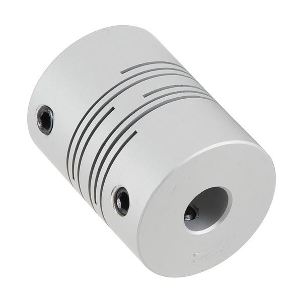
[22:30:56] <zeeshan|2> https://encrypted-tbn0.gstatic.com/images?q=tbn:ANd9GcRDLku-H78IpM_sDTXnZrilFkUR-RpbmcYghLPabYuGjIDgo5fj
[22:30:58] <zeeshan|2> er
[22:31:01] <zeeshan|2> http://i01.i.aliimg.com/img/pb/205/450/408/408450205_777.jpg
[22:31:08] <zeeshan|2> is it true that these type of couplers have a lot of backlash
[22:31:10] <skunkworks_> but it wasn't hydraulic cylinders - hydraulic motors..
[22:31:11] <zeeshan|2> > 0.001
[22:31:51] <tjtr33> the accupin is very cool, i think we can make those diy with printed circuits
[22:32:25] <skunkworks_> http://electronicsam.com/images/KandT/conversion/hyservo.JPG
[22:32:48] <pcw_home> Moog valve --> hyd motor?
[22:33:08] <skunkworks_> I don't remember if they are moog.. I think they where vickers..
[22:33:15] <skunkworks_> or maybe rebranded
[22:33:17] <skunkworks_> yes
[22:33:52] <skunkworks_> I think they had little buzzers in them to keep the valve from sticking
[22:34:05] <tjtr33> yes most 'dither'
[22:35:01] <skunkworks_> I think the cincinati lathe had the dithering in the servo amp. something like a 200hz signal on the analog to the valve
[22:35:36] <pcw_home> Yeah like tapping the analog meter...
[22:37:08] <skunkworks_> right. figure that is halable...
[22:37:28] <pcw_home> zeeshan|2: I know the aluminum ones are fairly fragile...
[22:38:34] <tjtr33> haha tapping big ol simpson meters
[22:38:40] <skunkworks_> (might try to get the Cincinnati running on hydraulic servos...
[22:38:50] <zeeshan|2> pcw_home: damn it
[22:38:51] <zeeshan|2> ;[
[22:38:53] <skunkworks_> they are just so big...
[22:39:08] <zeeshan|2> what about solid couplers? :]
[22:39:32] <zeeshan|2> snapped stepper shafts? :]
[22:48:31] <tjtr33> well the cou[plers you mentioned dont have a _lot_ of backlash , but there are stiffer ones w/o going solid. look at bellows and collet types ( Ruland & R+W are mfctrs)
[22:49:36] <tjtr33> the drawback to solid is that the 2 shafts have to be perfectly colinear ( to some degree of perfect, the error is just eating your bearings )
[22:49:48] <zeeshan|2> yea
[22:50:57] <skunkworks_> make one? ;)
http://electronicsam.com/images/KandT/conversion/yaxis/adaptfinal2.JPG
[22:52:00] <skunkworks_> made from a circle saw blade..
http://electronicsam.com/images/KandT/conversion/yaxis/flexplate.jpg
[22:52:21] <XXCoder> nice recycling
[22:53:03] <skunkworks_> heh - someone remade 99 red ballons..
[22:53:35] <skunkworks_> 'gold finger'
[22:54:07] <moorbo> skunkworks_: like
[22:54:10] <moorbo> 20 years ago
[22:54:37] <skunkworks_> really? huh.
[22:55:31] <skunkworks_> well - 2000
[22:55:53] <skunkworks_> never heard it
[22:56:10] <moorbo> skunkworks_: almost 20, heh
[22:56:24] <moorbo> I remember it on...crazy taxi for the dream cast
[22:56:36] <moorbo> I think anyways
[22:56:41] <moorbo> might have been a soncic gam
[22:56:42] <moorbo> e
[22:56:43] <moorbo> I forget
[23:01:01] <jp_mill> what would cause me not to be able to open up a file in axis? did i forget something basic in my ini?
[23:01:43] <FrankZappa> hey gents... sorry to interject. Wondered if anyone did any setups for tube bending they'd like to share.
[23:02:02] <XXCoder> hm
[23:02:03] <FrankZappa> I'm considering torches
[23:02:17] <zeeshan|2> madrel bent
[23:02:17] <XXCoder> I wonder if good cnc is accurate enough to MAKE circular saws
[23:02:18] <zeeshan|2> or crush bent
[23:02:28] <XXCoder> probably have to do two sides but..
[23:02:45] <zeeshan|2> *mandrel
[23:53:17] <tjtr33> linuxcnc tube bender by acemi
http://www.youtube.com/watch?v=ghDhZxidomc
[23:53:35] <XXCoder> 20 minutes ago
http://www.smbc-comics.com/index.php?id=3337#comic
[23:53:54] <tjtr33> i found 4 linuxcnc tube bender videos on youtube