Back
[01:38:52] <Haohmaru> uhm, according to a page at nongnu.org/avr-libc/ ... avr-gcc supports Ada, but when i do avr-gcc -v - it says it includes languages c,c++ (this is avr-gcc from atmel)
[02:12:23] <cehteh> the ada compiler is named 'gnat'
[02:12:47] <cehteh> 'supports' may not mean that you have it build/installed :)
[02:21:14] <Haohmaru> yeah, figured.. it appears it's available sepparately from sourceforge, but it looks unfinished
[02:25:02] <cehteh> i never used ada
[06:58:44] <pwillard> Ada is Pascal's cousin that joined the US Navy.
[07:14:37] <DKordic> xD
[07:23:37] * cehteh thinks one should put some efforts into making a more safe C runtime
[08:16:43] <Haohmaru> yo, i heard u like some plus over your C. so i put two.
[08:17:08] <LeoNerd> You likely heard wrong ;)
[08:17:37] <Haohmaru> don't question xzibbit's use of funny subtances
[08:18:38] <cehteh> with safe C i didnt meant to make it so much complex that no one can use it anymore :D
[08:39:46] <skz81> <Haohmaru> don't question xzibbit's use of funny subtances >> you should write "YO DAWG !!!" instead of "yo" for a better locutor identification ;°)
[08:40:31] <Haohmaru> sorry, i forgot how to DAWG
[08:41:07] <skz81> and I like safe "Cxx" (nearly "sex" phonetically ? No ? Ok, back to bed^W work)
[09:06:40] <_ami_> i got few motors (5 bi-directional, 3 uni-directional) to control. To control bi-directional motors, i can have 2 pins of MCU which controls it with the help of transistors/relays. is there any simpler way of doing it? any IC for it?
[09:07:20] <LeoNerd> For slow stuff like that I often use a shift register or an I²C expander
[09:07:23] <rue_house> transistors and opto-isolators if you need them
[09:07:38] <LeoNerd> Which comes usually pretty cheap or free, depending on what other IO you're doing
[09:07:41] <rue_house> did you want to improve switching time? use less io?
[09:10:17] <_ami_> rue_house: i want to have FAST switching time. i got enough i/o pins
[09:10:28] <_ami_> https://pbs.twimg.com/media/CxOvCmQUkAAM0M8.jpg:large
[09:10:33] <_ami_> i was thinking of something like this.
[09:10:47] <_ami_> should have made a schematic in kicad
[09:10:56] <_ami_> and share here.
[09:11:28] <_ami_> plz let me know if its not clear, i shall make a schematic in kicad and then ask. :)
[09:14:50] <_ami_> LeoNerd: i think shift register would be slow
[09:15:01] <LeoNerd> How fast are your motors?
[09:15:22] <LeoNerd> You can control the outputs of a shift register at hundreds of kHz at least
[09:15:28] <LeoNerd> That's 10µsec
[09:15:35] <LeoNerd> Physical motors won't need to react anywhere near that fast
[09:16:13] <rue_house> _ami_, for on/off or forward/reverse
[09:16:43] <rue_house> no, I suggest..
[09:17:07] <rue_house> a relay for reversing (dual pole, dual throw) and a mosfet for on/off
[09:17:30] <rue_house> the relay is low voltage drop and easy to use, the mosfet has fast on/off switching
[09:17:40] <rue_house> stand by
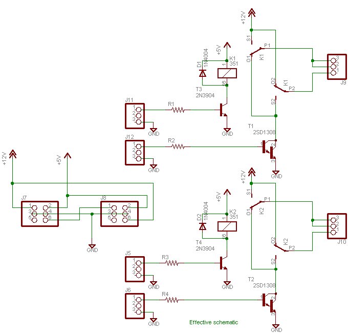
[09:18:49] <rue_house> http://ruemohr.org/~ircjunk/circuits/dc_ctrl3_sch.jpg
[09:18:55] <skz81> I drove some low-power DC moter from darligton H bridge, they came in DIP package
[09:19:00] <rue_house> thats not the diagram I'm looking for, but shows the basic idea
[09:19:14] <rue_house> a darlington bridge will drop a few volts
[09:19:27] <rue_house> and you have the fun of driving everyone
[09:19:44] <rue_house> if you dont need a fast turn-around time for reversing, a relay is nice
[09:20:17] <rue_house> for on/off switching, a mosfet like the IRFZ44 is nice
[09:20:28] <rue_house> low voltage drop, fast enough for pwm
[09:20:52] <skz81> rue_house, what do you mean, "drop a few volts" (maybe naive, but actual question)
[09:21:38] <rue_house> when a darlington is 'on' theres, depending ont eh transistor, from 1 to 3V across it
[09:23:38] <rue_house> are the motors being run at 10V or more?
[09:24:11] <_ami_> rue_house: 12v
[09:24:48] <rue_house> also, usually, you just switch the - side of the relay, which saves you half your transistors
[09:25:09] <LeoNerd> Or use a PNP on the top
[09:25:15] <rue_house> no
[09:25:28] <rue_house> cause then you need antoher transitor to drive that
[09:25:31] <rue_house> voltage differences
[09:25:46] <rue_house> if you just switch the - side, you only need an npn
[09:25:58] <rue_house> THO
[09:26:14] <rue_house> your coils are 5V, so thats less of an issue with a pnp
[09:26:52] <rue_house> ... why do your relays ahve 3 control leads?
[09:27:14] <rue_house> ... wtf...
[09:27:29] <LeoNerd> latch relays?
[09:27:57] <LeoNerd> You can get bistable relays that have two coils, one to push each way, and are bistable in either position
[09:28:10] <rue_house> I think this is just confusion
[09:28:18] <_ami_> rue_house: which one?
[09:28:19] <LeoNerd> I imagine such a relay would use a common line for one side of each coil
[09:28:25] <_ami_> relay1?
[09:28:34] <rue_house> _ami_, the top two relays have an extra wire
[09:28:50] <rue_house> gnd, vcc, s, in, out
[09:28:53] <rue_house> ?
[09:30:52] <rue_house> .. cant find a diagram of what I'd suggest
[09:31:12] <rue_house> how much current do your motors need?
[09:31:21] <_ami_> S - input from mcu, in - external circuit input, out- external circuit output , Vcc -- power up the relays ,lower side voltage, gnd - lower side gnd.
[09:31:37] <rue_house> see that dosn't add up
[09:32:12] <rue_house> esp cause its only on k1 and k2
[09:32:48] <_ami_> rue_house: i would be using
http://ecx.images-amazon.com/images/I/71G4MLhPGGL._SL1100_.jpg relays board for that.
[09:33:26] <rue_house> ok
[09:33:33] <rue_house> that makes more sense then
[09:34:13] <rue_house> so, you can put the arduino inputs directly to that
[09:34:24] <rue_house> no transistors or diodes needed
[09:34:51] <Chillum> I copy the design on those boards in my own projects
[09:35:03] <Chillum> though I tend to have wider isolation in my boards
[09:35:20] <Chillum> and a fuse
[09:35:36] <rue_house> _ami_, so, did you want to do speed control? what are you looking for here
[09:35:50] <Chillum> you would think for the product shot they would use one that had good soldering, that diode looks sketchy
[09:36:01] <_ami_> rue_house: no speed control. just on/off the motor and change the direction if required.
[09:36:08] <rue_house> you can use just 2 relays per motor ya know
[09:37:21] <_ami_> rue_house: for bi-directional motors also? 2 relays would be enough. i think i made it too complex.
[09:37:25] * _ami_ sighs.
[09:37:28] <rue_house> I cant find the diagram
[09:37:38] <rue_house> and I have no time to make one right now
[09:37:44] <rue_house> so ""
[09:37:57] <_ami_> ok, i will google.
[09:38:00] <rue_house> the common from each of two relays goes to a motor terminal
[09:38:39] <rue_house> the motor negitive supply, goes to the normally closed of both relays
[09:38:54] <rue_house> the mtoor positive supply goes to the normally open of both relays
[09:39:11] <rue_house> k1 k2
[09:39:16] <rue_house> off off stop
[09:39:26] <rue_house> off on (CW)
[09:39:33] <rue_house> on off (CCW)
[09:39:40] <rue_house> on on stop
[09:40:11] <Haohmaru> i predict 50% chance for "stop" ;P~
[09:42:38] <skz81> hum, on/on is active breaking and off/off free-wheeling, isn't it ?
[09:42:55] <rue_house> not with that
[09:42:59] <rue_house> both brake
[09:43:37] <rue_house> with two diodes you can have it freewheel (diodes in the lines from normally-open to +V)
[09:43:53] <rue_house> but you add 0.7V drop
[09:48:23] <_ami_> thanks rue_house, i made a note of it.
[09:51:29] <rue_house> let me guess, your the project software guy?
[09:55:48] <_ami_> rue_house: i got a freelancing project. i am basically mostly a software guy! :)
[09:56:36] <_ami_> its gonna be a product and excited to make it deliver! demo is in january. lets see how it goes.
[09:56:47] <rue_house> your question had "I'm a software guy telling th hardware guy how to do his thing" written all over it
[09:57:08] <_ami_> :D
[09:59:08] <_ami_> hw is really hard.. and its harder if you are not doing it regularly. i hv learned most of thing by googling/asking here/referencing electronics books sometimes.
[09:59:27] <_ami_> refering*
[10:42:56] <cehteh> _ami_: use some H-bridge driver, not relays
[10:44:07] <cehteh> relays have a short unpredictable delay, you will have some split seconds where they may generate shorts
[10:44:48] <cehteh> or use use relays with double throw which are mechanically coupled so this can not happen
[10:45:04] <cehteh> then one relay for direction and one for on/off
[10:52:08] <cehteh> http://tinyurl.com/zfgyl5f
[10:52:10] <_ami_> cehteh: okay,
[10:52:31] <cehteh> but when you use DC motors .. then H bride
[10:52:46] <cehteh> makes no much sense to use relays
[10:54:29] <_ami_> you are absolutely correct. no need of relays
[10:55:18] <cehteh> what motors? size/voltage/current?
[10:55:48] <cehteh> http://www.banggood.com/Dual-Channel-L298N-DC-Motor-Driver-Board-PWM-Speed-Dual-H-Bridge-Stepper-Module-p-1064434.html
[10:57:07] <_ami_> 12 V / (1A - 3A max)
[11:51:27] <noqnio1> hey, while i was setting the fuses on a m48pa, it stopped responding and every time avrdude reads a different signature and gives me an rc=-1 error
[11:51:41] <noqnio1> I didn't mess around with any dangerous fuse
[11:52:44] <learath> How sure of that are you?
[11:53:50] <noqnio1> I think i am quite sure, the fuses were e:01 h:DF l:E2 and i tried to write FF on the low fuse, on a atmega48pa
[11:53:54] <noqnio1> damn emoticons
[12:01:34] <noqnio1> never mind, it turns out im an idiot
[12:18:24] <antto> noqnio1 did you disable SPI?
[12:23:18] <noqnio1> no i had the cables wrong !!!
[23:31:29] <sabor> _ami_, cehteh: L298 is a stoneage chip, at 1A load you get a voltage drop between 1.8V and 3.2V according to the datasheet, so from the 12V only about 9-10V are arriving at the motor
[23:32:17] <cehteh> yeah i gave that only as example, there are plenty more