Back
[01:52:54] <superware> is there an AVR MCU with Ethernet support?
[02:01:03] <superware> everyone're asleep?
[02:11:51] <Xark> superware: No, but you can do a half-ass bitbang of ethernet. :)
[02:12:17] <superware> :) how?? enough to send a UDP packet?
[02:12:58] <Xark> http://hackaday.com/2014/08/29/bit-banging-ethernet-on-an-attiny85/
[02:21:39] <superware> Xark: thanks, loved the "really, don't use this project" (completely unstable etc)
[02:22:19] <Xark> Well, I did mention "half-ass", didn't I. :D
[02:22:59] <superware> heh
[02:24:23] <superware> any experience with ENC28J60?
[02:27:21] <Xark> I have used it very little, but it seems to work okay.
[02:28:22] <Xark> Several libraries around (since it does require a fair bit of software support).
[02:30:11] <superware> I see
[02:36:41] <Xark> I think there is even a full Linux driver for it via SPI (since it sends raw packets). :)
[02:37:24] <Xark> (Not that it is too useful for AVR, but shows ENC... chip is versatile). :)
[03:00:57] <superware> is there a common dev board that will allow me to sample 6 ADC channels and send Ethernet UDP packet?
[03:01:13] <superware> maybe a single MCU with Ethernet support?
[03:23:20] <Haohmaru> if you need tcp/udp as well, an option is wiznet's w5500 which has tcp/ip stack
[03:26:37] <superware> yeah
[03:51:14] <lowin> Is it pronounced aah tee mega or ayy tee mega or at-mega?
[03:52:06] <Haohmaru> just use xmega, then you can't pronounce it wrong >:)
[03:52:19] <Haohmaru> EKSMEGA
[03:52:58] <lowin> That's one way to go I suppose
[06:08:11] <Lambda_Aurigae> superware, tuxgraphics has a nice tcp/ip stack for atmega and enc28j60
[06:08:22] <Lambda_Aurigae> superware, as well as dev boards.
[06:08:40] <Lambda_Aurigae> http://www.tuxgraphics.org/electronics/200905/embedded-tcp-ip-stack.shtml
[06:08:55] <Lambda_Aurigae> http://tuxgraphics.org/electronics/200606/article06061.shtml
[06:09:09] <superware> thanks man!
[06:09:14] <Lambda_Aurigae> welcome.
[06:09:38] <Lambda_Aurigae> I've used it several times. Just mod one of their projects to do what I want.
[06:10:37] <Lambda_Aurigae> they use relatively small atmega chips like the 88 or 168
[06:10:54] <Lambda_Aurigae> I like to use the atmega1284p with lots of ram.
[06:11:31] <Lambda_Aurigae> I even did an ethernet based bootloader for the 1284p once just for the fun of it.
[06:20:29] <superware> cool
[06:20:52] <Lambda_Aurigae> they even use the clkout pin from the enc28j60 to provide stable clock source for the avr.
[06:21:25] <Lambda_Aurigae> and that can be changed in software..it starts out at 6.25MHz by default using a /4 prescaler
[06:22:30] <Lambda_Aurigae> so you can go up to 12.5MHz with no problems. I've taken the atmega1284p up to the full 25MHz but had little issues with the ADC at that speed as it's rated max is 20MHz.
[06:34:17] <superware> I need this for ADC...
[06:34:39] <superware> but I guess the internal 8MHz will do
[06:37:43] <Lambda_Aurigae> depends on what you are doing.
[06:38:02] <Lambda_Aurigae> if you want to do any USART comms, the internal RC oscillator is not exactly all that stable.
[06:38:23] <Lambda_Aurigae> so running it from the enc28j60 clock output at 12.5MHz would be better.
[07:04:47] <superware> I only need 6 ADC channels
[07:08:35] <Lambda_Aurigae> now, you know that the AVR only has one ADC with a multiple input switch, yes?
[07:08:40] <Lambda_Aurigae> and
[07:08:45] <Lambda_Aurigae> I gotta go to work now..laters.
[07:12:11] <Tom_itx> which is it? now or later????
[07:26:18] <superware> really?! so if ATmega328P says "15kSPS at max res" then it's actually 15k/6?
[07:26:58] <twnqx> if you use all 6 channels, yes
[07:27:11] <twnqx> if you only use one, it's 15k
[07:28:43] <superware> and what's 76.9kSPS?
[07:29:54] <twnqx> possibly a result with less precision?
[07:30:03] * twnqx doesn't bother to look in to the data sheet
[07:30:41] <superware> yeah, 8 bit
[08:07:17] <jaggz> I'm trying to find a page with an example of setting up PWM for making noise on a piezo speaker... anyone have a reference for me?
[08:07:48] <jaggz> (coding with avr gcc, not arduino)
[08:18:12] <liwakura> consult the datasheet of your device
[09:06:34] <rue_bed> jaggz, yup
[09:06:51] <rue_bed> oh, using pwm
[09:06:52] <rue_bed> hmm
[09:07:08] <rue_bed> you just wnt to make tones?
[11:08:16] <bss36504> How the heck does the xmega event system work? I feel like it's useful but I cannot think of a real world example where youd use it. I see you can select the source channel, and theoretically another peripheral can use that information...so could I use an ADC conversion complete to trigger a DMA to a SPI transfer?
[11:09:45] <cehteh> http://monster6502.com/ cool
[11:09:59] <bss36504> Of course, now I see that the DMA seems to have a separate trigger for almost, if not all, of the other peripherals, so maybe even system isnt necessary for that?
[11:10:25] <cehteh> i havent used xmegas yet
[11:11:36] <bss36504> cehteh: Well that's a pretty neat project.
[11:12:15] <bss36504> I want to love the xmega so much, but I can't quite understand this event system. And I realize that the even system is a fairly common atmel periph; unless I'm mistaken the samD20 has it too.
[11:17:44] <cehteh> iirc stm32 has some event system too
[11:17:58] <cehteh> but i dont know enough details to help you out
[11:18:19] <cehteh> you are just working on your ovenß
[11:18:20] <cehteh> ?
[11:18:37] <bss36504> Yeah, I'll still use the xmegaA4U, I was just curious
[11:18:41] <cehteh> .. simple 328p based bord would be enough for that
[11:19:13] <bss36504> Oh I know, but in order to do the neato phase control with the DAC and the AC, I'd like the xmega.
[11:21:12] <bss36504> I also plan to have two thermocouples, connected to two SPI thermocouple amps (MAX31855). Since the 16/32A4U have two SPI ports, I was going to make one a master, one a slave. Master commands both amps to read, one clocks its data into the master, the other clocks into the slave SPI port. Simultaneous read FTW. No, it's not necessary, just cool
[11:23:14] <bss36504> Maybe I'll do something with DMA just for funsies so that when a SPI packet comes in, the DMA can move it to the correct memory location so all I have to do is read from the TC amp.
[11:27:51] <cehteh> heh
[11:28:10] <cehteh> well yes, but try to make it work first and keep it simple
[11:28:26] <bss36504> Oh of course.
[11:28:39] <bss36504> I just like that there are so many peripherals.
[11:28:59] <bss36504> The DMA stuff is well outside the scope of "making it work".
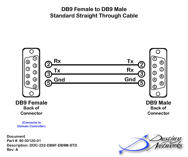
[12:32:31] <oo_miguel> I have a stk500 board, but I lost the serial cable to connect it to my pc somewehre. However I have two d-sub connectors, and wonder how to wire them to work as a transmission cable between the board and my pc
[12:40:09] <oo_miguel> ok, I guess this should work right?
http://www.turn-n-burn.com/DestinyNetworks/Downloads/WebHelp3-1-1/Images/4_Design_and_Installation/4_Cables/Domain_3000_Cables/120-DB9M-STD.gif
[12:47:56] <lowin> oo_miguel, Thats the basic kind of null modem cable. It'd work if the board doesn't rely on any other line
[12:49:06] <twnqx> it also only works if both sides have the same gender
[12:52:43] <AltSheesh> Has anyone in here done an ATMega8U2 project that's like a HID, only I will need some way to talk to the ATMega to set it up during operation? Had an idea but not sure if it's doable, yet. (Haven't done any USB stuff, just older serial etc. embedded stuff.)
[12:55:36] <lowin> AltSheesh, not sure I understand. You want to make a usb device that is classed as a HID device but also want some way to control the device in a way other than regular HIDs ?
[12:58:25] <AltSheesh> yes; I wasn't sure if I can send anything to an HID device (I know you can with a ps2 keyboard.) Figuring out where to look still
[13:01:58] <lowin> AltSheesh, USB spec allows multiple endpoints on the same interface. You can designate an endpoint to be what you'll send your commands to
[13:02:53] <AltSheesh> http://www.usb.org/developers/hidpage/HID1_11.pdf should help; OK, so its doable, good :)
[13:03:39] <bss36504> LUFA has multi endpoint example code.
[13:04:43] <bss36504> No reason you couldnt put a serial endpoint and an HID endpoint in the same physical USB device. Or HID and MSC, or any other combo. It will enumerate as two "devices" on your computer, though I think the comp technically knows it's a composite device.
[13:04:57] <aandrew> that isn't entirely true
[13:05:01] <aandrew> in theory you are 100% correct
[13:05:32] <bss36504> Im not a USB expert, enlighten me
[13:05:45] <aandrew> I think it's the windows HID driver that *requires* the HID endpoint to be the first endpoint listed. if you just change the endpoint number and update the descriptor accordingly it will just stop working without any explanation
[13:05:57] <aandrew> I'm pretty sure it's HID. I ran into this exact issue in some of my PSoC work
[13:06:04] <aandrew> it was maddening
[13:06:05] <aandrew> er not
[13:06:07] <aandrew> not HID
[13:06:11] <aandrew> it was CDC
[13:06:18] <aandrew> the CDC endpoints (there are two) must be the first two endpoints
[13:06:24] <bss36504> Oh interesting. That would be a subtle gotcha haha
[13:06:34] <aandrew> if you have some VS endpoint and wanted it as the first endpoint, you're SOL
[13:06:42] <aandrew> the CDC endpoints had to be first
[13:07:02] <bss36504> I haven't actually made a composite device, only ever did a MSC, but i just knew in theory it should be possible
[13:07:03] <aandrew> it was very infuriating because everythign was right, it was just the order that was wrong
[13:07:24] <aandrew> maybe carebear on #libusb could shed some light on why, but I think it was just a hardcoded requirement in the Windows CDC driver
[13:07:44] <bss36504> Make it a, what is it, bulk only? Then write a custom driver for the non-HID side of it
[13:08:06] <aandrew> hm?
[13:08:32] <bss36504> I thought there was some raw USB class that just allowed you to send packets, but would require driver support on the computer side
[13:08:38] <bss36504> (and I suppose on the micro too!)
[13:09:29] <aandrew> oh, I think I'm wrong again
[13:09:30] <AltSheesh> I suspect I'll be learning a lot here - It'll be nice to stretch my brain tho :) How would you watch the data going back & forth to & from my device, is there a usual tool or should I just put a serial port on the beastie? I need it to type into a running program, so cant really be a bulk device
[13:09:44] <aandrew> looking at my git logs for that project it wasn't the windows drivers, it was the OSX CDC driver
[13:10:12] <aandrew> bss36504: well if you're not advertising for a specific class, you just have vendor specific (VS) endpoints and then you're on your own
[13:10:37] <AltSheesh> IDK what cdc stands for (I know it won't be control data corp. :P Used to use their mainframes long ago) yet
[13:10:41] <aandrew> AltSheesh: if you don't want to write and debug your own USB code, stick an FT232 or Prolific chip on the board and wire it up to your UART
[13:11:20] <AltSheesh> I can do the usb code too, should be able to do it.
[13:11:27] <aandrew> the beauty of CDC is that it's driverless in that everything has a driver for it and you don't have to piss around with drivers as well
[13:11:40] <aandrew> there's tons of code out there for all the different platforms for CDC
[13:11:58] <AltSheesh> i'm an older guy, coding since the 70s, just new to usb coding :)
[13:12:12] <aandrew> one of the first things I tend to do is to instantiate USB CDC and "wire" the standard IO to it so I can just printf() a lot of the etime for debugging
[13:12:48] <aandrew> AltSheesh: no worries, you're a little older than me (40 this year) and USB is a bit much to get started in but once you've got your USB cranial bruises it's fine
[13:13:35] <AltSheesh> I'd put a terminal on a laptop to the avr or something; lots of laptops here LOL - More brain contusions expected :p
[13:15:59] <AltSheesh> OK I think that'll be it for now (still up from last night) maybe can sleep now :)
[13:16:04] <bss36504> CDC = Communications Device Class
[13:16:37] <aandrew> AltSheesh: I usually idle here and #hackvana and #libusb; lots of help out there
[13:18:25] <bss36504> oh just a heads up, if you just want HID and device firmware update, there is a DFU class. so you could avoid the CDC-as-first-endpoint shenanigans.
[13:19:13] <aandrew> I've not yet experimented with DFU class. I really should
[13:45:10] <AltSheesh> Mainly I want to avoid having to write system drivers on every available PC OS like the plague :p
[13:49:21] <jaggz> AltSheesh, I probably need to switch from LUFA to some other usb library because of that
[13:49:28] <jaggz> I just need to emulate mouse and keyboard
[13:50:17] <bss36504> Why does LUFA force you to write PC drivers?
[13:50:59] <jaggz> no.. lufa's not working in windows..
[13:51:20] <jaggz> sorry, didn't explain (had the discussion before in here and didn't want to trouble the entity of the channel by repeating it)
[13:51:48] <bss36504> Oh oh gotcha
[13:51:51] <jaggz> currently I'm just using usb-serial support in LUFA, when designing my device.
[13:52:04] <jaggz> In windows, however, each time I plug it in I have to set the COM settings again
[13:52:36] <jaggz> and setting them in the device manager doesn't change them for some reason.. the only thing I've found that works is to run mode com5 etc. etc.
[13:53:11] <jaggz> actually you may have solved my problem.. the lufa kb and mouse support may work fine :)
[13:53:33] <jaggz> I'm glad we sat down and had this talk, bss36504.
[13:54:01] <jaggz> 8-bit Timer/Counter0 with PWM is this the proper chapter for PWM, or is it a timer chapter?
[13:54:25] <jaggz> datasheets confuse me still.. I'm just getting into AVR programming..
[13:55:08] <LeoNerd> PWM is a function of the timer units
[13:57:31] <jaggz> okay.. and then they start using terms like "Output Compare Units".. and then the TCNT0 --
[13:57:37] <jaggz> so now I'm looking up TCNT0 to see what that is
[13:57:46] <jaggz> a clock cycle counter? (can't find it yet)
[13:58:23] <AltSheesh> I was talking about the bulk usb device style, that iirc ends up you have to write system level device drivers?
[13:58:29] <bss36504> TCNTx is the current count of the timer
[13:58:35] <LeoNerd> Timer CouNT for timer unit 0
[13:59:38] <bss36504> depending on your WGM (waveform generation mode) bits, different things will happen when TCNT reaches TOP, BOTTOM, or matches your Timer compare register
[14:00:11] <jaggz> okay.. and, for PWM, it fires an interrupt when that reaches a max value, and uses that for determining whether to set the PWM output high or low? (along with other calculations for the frequency and duty cycle)
[14:00:23] <LeoNerd> The output module is independent of interrupts happening
[14:00:32] <LeoNerd> When the output compare matches happen, two independent activites happen
[14:00:44] <LeoNerd> 1) an interrupt might be fired, depending on the global I bit and the individual interrupt control flags of the timer unit
[14:00:47] <bss36504> Well, yes an interrupt can be serviced, but generally for PWM you just let the hardware in the output module take care of toggling the pin
[14:00:54] <AltSheesh> weirdly, I can't sign in to atmel.com atm, to dl atmel studio; IDK why LOL
[14:00:54] <LeoNerd> 2) the output compare unit might adjust the output pin's state
[14:01:11] <bss36504> AltSheesh: probably because their site suuuuucks
[14:01:19] <bss36504> Though not as bad as Autodesk
[14:02:07] <jaggz> LeoNerd, thanks
[14:04:47] <AltSheesh> LOL bss36504 well, I can get on other computers and DL on them, or worst case buy the DVD if I have to
[14:28:55] <jaggz> yayvr!
[14:37:31] <jaggz> I do believe I work best learning from examples.. not yet datasheets
[14:48:09] <oo_miguel> would I need extra hardware to let my tiny at90s2313 communiacte over a serial port?
[14:49:24] <oo_miguel> ah it seems it comes with a full duplex uart
[14:55:49] <RikusW> you'll need a level converter for rs232
[14:56:57] <Tom_itx> http://tom-itx.no-ip.biz:81/~webpage/misc_stuff/rs232_5.jpg
[14:57:01] <Tom_itx> or such
[14:57:41] <bss36504> Almost easier to just use a USB-serial converter unless your computer only has RS232 ports
[14:57:52] <bss36504> In which case, let us know how 1990 is.
[15:00:52] <oo_miguel> hmm it seems there is such thing on my porgramming board already
[15:01:53] <oo_miguel> max202 cse-something
[15:15:45] <carabia> i remembered max232 taking more caps than that
[15:17:31] <carabia> But I guess it didn't. Two for the charge pump and the two other for... Who cares
[15:19:54] <AltSheesh> 1990 is great, Dos 6.22 is wunnerful :)
[15:21:03] <carabia> It's really borderline - I'd say - if bss36504 was even born back in '90
[15:22:15] <AltSheesh> I was about then, still have XTs
[15:47:03] <bss36504> I was born post 1990 but pre 2000 ;)
[15:54:06] <Tom_itx> carabia some don't require any
[17:24:12] <LeoNerd> Randomly curious and never really got to the bottom of this before: does anyone know the purpose of the "UART receive start" interrupt? Why is this condition of interest?
[17:26:06] <LeoNerd> The other three UART interrupts (RX complete, TX complete, TX data register empty) all make sense to me, I can see why you want to know. But not the RX start
[17:30:01] <cehteh> dunno either, but possibly to do some preparation for the incoming byte or implement some software assisted serial protocols
[17:36:15] <LeoNerd> Ooooooh... here's a thing
[17:36:31] <LeoNerd> Reading a different MCU's data sheet that also has a start condition, they suggest you could use it for adjusting or switching clock sources
[17:37:05] <LeoNerd> because on the AVR, the UART start condition detector can work asynchronously without a clock. so maybe you need to enable the full MCU clock and set the prescaler correctly, so the baud generator works at the right speed
[17:37:05] <jaggz> 2<<COM0A0: sets bits COM0A0 and COM0A1, which (in Fast PWM mode) clears OC0A on compare-match, and sets OC0A at BOTTO
[17:37:32] <jaggz> Does it? 2<< sets two bits??
[17:37:53] <LeoNerd> Doesn't, nope
[17:38:04] <LeoNerd> I'd do that with _BV(COM0A0)|_BV(COM0A1)
[17:38:12] <CasperAtWork> 2<< = 0b00000010
[17:38:14] <jaggz> Do they just mean they're ignoring bit 0, leaving it 0, and they're staying it badly?
[17:38:57] <jaggz> http://matt16060936.blogspot.com/2012/04/attiny-pwm.html?m=1
[17:39:16] <jaggz> Still working on learning pwm, btw
[17:39:27] <cehteh> 3<< would set 2 bits .. but dont do that
[17:42:59] <jaggz> Right
[17:47:23] <aandrew> no
[17:47:38] <aandrew> 2<< moves binary "10" however many bits
[17:47:42] <jaggz> What's a timer prescalar?
[17:47:54] <aandrew> jaggz: well a timer has a clock
[17:48:00] <aandrew> every time the clock ticks, the timer increments
[17:48:07] <aandrew> a prescaler sits between the clock and the timer clock input
[17:48:25] <aandrew> and every 'n' clock ticks will generate 1 tick out (generalized, not exactly how it works)
[17:48:34] <aandrew> it's a nice way to divide down the incoming clock
[17:48:41] <aandrew> so let's say you have a 1MHz clock feeding an 8 bit timer
[17:48:43] <jaggz> Cool
[17:48:49] <aandrew> 1Mhz has a 1us period
[17:48:52] <jaggz> Integer divisor?
[17:49:01] <aandrew> 8 bits means it overflows in 256 ticks
[17:49:02] <jaggz> Ok.. go on
[17:49:07] <aandrew> so 256us maximum
[17:49:29] <aandrew> if you have a prescaler that can divide by 4 (for example) now your timer will overflow in 256*4 ticks
[17:50:04] <aandrew> almost all prescalers are integer
[17:50:07] <jaggz> So it's used to give a higher period for the timer counter?
[17:50:28] <jaggz> So counter (timer) accounts for a longer period of time
[17:50:54] <aandrew> 2correct
[17:53:14] <jaggz> Thanks :)
[17:54:33] * CasperAtWork throws warm air at jaggz
[17:54:46] * CasperAtWork replaces a << with a >> in jaggz's code
[18:14:48] <aandrew> fjfjf
[18:19:07] <jaggz> CasperAtWork, !
[18:19:16] <CasperAtWork> hellow!
[18:20:15] <jaggz> uint8_t r=0; if (++r>255) r=0;
[18:20:19] <jaggz> Really??
[18:28:12] <aandrew> jaggz: wtf
[19:30:23] <jaggz> I'm not sure if this guy's page is the best role model for me to learn PWM
[19:30:29] <jaggz> heh
[19:30:30] <jaggz> http://matt16060936.blogspot.com/2012/04/attiny-pwm.html
[19:31:12] <jaggz> Casper, I don't know how to make sense of datasheets
[19:31:19] * Casper runs
[19:31:25] * Casper actually goes nap
[19:31:28] <jaggz> it's like looking at unix man pages from the late 80's / early 90's
[19:31:42] <jaggz> no examples
[19:31:50] <jaggz> Casper, fine be that way
[19:32:19] <jaggz> :)
[19:33:55] <jaggz> nobody else documents it as well.. even though there are some oddnesses and inaccuracies in it
[19:34:00] <jaggz> well.. I can't find a good page on it anyway
[20:33:00] <Lambda_Aurigae> jaggz, no examples? AVR datasheets are full of examples.
[20:33:29] <Lambda_Aurigae> and, yes, reading a datasheet is much like reading a manual. You should read it cover to cover first, then go back and hit the highlights.
[20:36:13] <Snert> and after a few brews, read it again :)
[20:40:50] <jaggz> bleh.. I need to get this project working so I can study
[20:40:58] <jaggz> just making a piezo alarm for the fridge
[20:41:41] <jaggz> the door's not shutting all the way unless you push it.. and water's going on the floor from the temperature rise (and additional thawing and condensation in the freezer)
[20:42:05] <Lambda_Aurigae> I would fix the fridge myself.
[20:43:25] <jaggz> yeah it needs a new seal
[20:43:40] <jaggz> I've already adjusted its levelness to try to angle it back, but I think the seal is bad
[20:48:00] <jaggz> Lambda_Aurigae, also I want to learn how to program these things :)
[20:48:25] <Lambda_Aurigae> I learned by reading the datasheet then reading the avr-libc website.
[20:48:29] <jaggz> but I have such little background in it that I constantly run into terminology issues in the datasheet
[20:48:42] <Lambda_Aurigae> before there was such as thing as an avr irc channel even.
[20:48:49] <Snert> those lessen with time.
[20:49:07] <Snert> at first, a datasheet can be just full of good google terms.
[21:01:10] <Casper> jaggz: the datasheet have example for most stuff
[22:26:45] <_ami_> hey guys
[22:29:00] <Casper> hello
[22:29:02] <Casper> how's india?
[22:29:32] <_ami_> HOT! :D
[22:29:58] <Casper> must be
[22:30:38] <_ami_> btw, i studied UART on AVRs today. wrote a simple program to send/receive chars on Atmega16A (at 1MHz).
[22:30:39] <_ami_> https://github.com/amitesh-singh/amiduino/blob/master/avr/avr_programmming/serial/serial.c
[22:30:48] <Casper> I guess... you would find the current 22°C to be cold?
[22:31:03] <_ami_> i get the garbage text on serial console
[22:31:18] <Casper> do you use a crystal?%
[22:31:58] <_ami_> Casper: no.
[22:32:37] <Casper> that is probably your issue
[22:32:55] <Casper> the internal clock is not quite precise, specially on short term
[22:33:10] <_ami_> Casper: should i lower the baud rate?
[22:33:12] <_ami_> 2400?
[22:33:18] <Casper> so bit to bit it can vary alot
[22:33:25] <_ami_> try it on 2400?
[22:33:29] <Casper> if you can, use a crystal
[22:33:45] <Casper> what is your current clock speed?
[22:33:52] <_ami_> 1MHz
[22:34:23] <Casper> http://wormfood.net/avrbaudcalc.php
[22:34:30] <Casper> max is 4800 that can work
[22:34:34] <Casper> but try 2400
[22:34:52] <Casper> and you can try to tune up and down the divider a bit if it still fail
[22:34:59] <_ami_> ok
[22:38:53] <_ami_> Casper: btw, where do you live?
[22:39:04] <Casper> canada
[22:40:01] <_ami_> cool.
[22:40:37] <Casper> you should come here in january
[22:40:39] <_ami_> its always cold there? 8 months in a year?
[22:40:53] <Casper> we only get like -30°C...
[22:41:07] <Casper> summer is like +30C
[22:41:13] <Casper> and winter -30C
[22:41:26] <_ami_> Casper: it works!! i repeat it works at 2400! wow!
[22:41:29] <_ami_> thanks
[22:41:49] <_ami_> -30 is brutal.
[22:42:11] <_ami_> 50 for us during summer. :( brutal
[22:42:30] <Casper> I prefer cold to hot
[22:42:39] <Casper> atleast you can add a layer and feel ok
[22:43:14] <_ami_> indeed.
[22:43:33] <Casper> the worst for me is the -5°C...
[22:43:52] <Casper> hot enought that the sun make the window of your car hot enought to melt snow
[22:44:00] <Casper> but then as soon as the sun is gone... it freeze
[22:45:40] <_ami_> Casper: hire me then i will come to Canada! :)
[22:45:41] <_ami_> haha
[22:45:52] <_ami_> it would be an upgrade for me. :D
[22:46:08] <_ami_> does Canada have IT companies? software stuffs
[22:46:14] <Casper> sure
[22:46:19] <Casper> like ubisoft montreal
[22:47:42] <_ami_> cool. one of my college batch mate runs a startup in Canada.
https://www.loginradius.com/
[22:49:41] <Casper> something is not right
[22:49:59] <Casper> a startup that have thousands of clients including banks?
[22:51:13] <_ami_> dunno
[22:51:48] <_ami_> his company was listed among top 15 startups in canada.
http://www.techvibes.com/blog/metabridge-names-15-of-canadas-hottest-tech-startups-2015-05-08
[22:53:59] <Casper> weird...
[22:54:20] <Casper> maybe the bank only requested a demo, thru "trusting"...
[22:54:39] <Casper> ... I would hope so...
[22:54:52] <Casper> ... can't trust a startup for bank stuff imo
[23:26:47] * Xark likes how a few boards use a little arrow for TX/RX (much less ambiguous).
[23:26:53] <carabia> _ami_: well, I'm not sure - and too tired to figure out - what's happening over there. But in any case I'd keep the mcu in reset or pull it off the socket if I wanted to use the ftdi-chip with another device
[23:27:16] <carabia> I don't own any arduinos so I can't really test it, no
[23:29:32] <carabia> Xark: well you don't have to trust the labeling. You can measure it. No ambiguity there
[23:32:52] <_ami_> https://forum.arduino.cc/index.php?topic=283043.0
[23:33:15] <_ami_> 0 is Rx and 1 is Tx in Uno , right?
[23:34:02] <Xark> Ye
[23:34:04] <Xark> s
[23:34:26] * Xark notes his RedBoard (Sparkfun Uno) has RX TX and arrows. :)
[23:34:56] <_ami_> please check the last comment at this discussion:
https://forum.arduino.cc/index.php?topic=283043.0
[23:35:06] <_ami_> 4) Connect TX-TX and RX-RX. Why? I don't know. But it works. After I did this, I started getting something back, even if garbage, without the correct serial baud settings.
[23:35:23] <Xark> :)
[23:35:52] <_ami_> i am not getting garbage.. i get the data correctly.
[23:37:11] <_ami_> i wanted to know why rx-rx and tx-tx in this case.
[23:39:03] <Xark> _ami_: Well, usually the issue as I mentioned is one of "perspective". For example on a PC -> USB serial converter, it is TX, but since it connects to MCU RX they may label it RX (just like I said, ambiguous without from which devices "perspective").
[23:39:34] <_ami_> so uno acts like a bridge here
[23:39:35] <_ami_> ?
[23:40:04] <Xark> Ignore the labels and look what is connected to what and it will make sense (in my experience).
[23:41:34] <Xark> Or as carabia suggests look for which pin is logic one (idle state for serial - usually, not always with TTL serial...)
[23:43:31] <_ami_> aha, you mean when MCU is off in Uno, Rx and Tx (labelled for 328P) position is swapped ?
[23:44:45] <Xark> No, it does not swap just because CPU is yanked or in RESET...
[23:45:41] <Xark> All, I am saying is despite e.g., connecting RX to RX *really* you are connecting output of one circuit into input of the other (input to input or output to output never "works").
[23:46:06] <_ami_> hmm, understood
[23:46:32] <Xark> This is why I mention RX/TX label is ambiguous (several times now). :)
[23:47:54] <Xark> You need "RX of MCU" or "RX of USB TTL adapter" not just "RX"
[23:48:10] <_ami_> hmm
[23:50:52] <Xark> So, pin 0 will be "RX of MCU", which is connected to "TX of USB serial adapter". Get it?
[23:51:27] <_ami_> Yup
[23:51:28] <carabia> Xark: what I meant was simply testing the pins with continuity :)
[23:51:43] <Xark> carabia: Multimeter?
[23:51:45] <_ami_> carabia: actually i was confused with the labelling :)
[23:51:49] <carabia> that's what i said.
[23:51:58] <_ami_> yeah :), thanks
[23:56:18] <Xark> I note that when designing FPGA circuits, this becomes real confusing. Like you make a CPU with "input" and "output" data lines, but then when working on the "system" module input will be an output (hence confusing). The solution is to name things like "data_from_CPU" "data_to_CPU" then it always "makes sense". :)