Back
[01:52:48] <day> what exactly does '#define __PROG_TYPES_COMPAT__
[01:52:51] <day> do
[02:40:51] <megal0maniac> what, Lambda_Aurigae? :P
[02:41:12] <megal0maniac> Got me grepping logs ;)
[02:41:39] <megal0maniac> Because of your frivolous tabbing
[02:58:00] <redspl> hoi
[06:59:14] <mike_papa> Hello. Could anyone briefly tell me pros and cons of using external interrupt instead of timer's capture mode for getting external signal time stamp? From what I've read, I've found out only two things: build in filter, and lower interrupt priority for timers 3,4 and 5 what could make a difference if you use USART0, USART1, comparator and TWI. I'm playing with atmega2560.
[07:50:00] <LeoNerd> So.. not strictly on an AVR topic, but more electronicsy; plus it's quiet... Current sense amplifiers. The sort that you put across a tiny resistor, to measure high-side current. I'm looking at working in the 5-500mA range.
[07:51:19] <LeoNerd> I've got myself some TS1102 chips, which seem to work quite nicely; they're reeeeally simple. Literally put it across a resistor, and its OUT pin voltage is proprtional to the current in the resistor. dead simple. But problem with this chip is it's a bit slow. I was wanting to measure up to around 1MHz bandwidth, at least something fast enough to see sharp transitions on my oscilloscope. But this thing has a >>
[07:51:19] <LeoNerd> << 50kHz 2nd order filter built-in, which is smudging out the reading
[07:53:57] <LeoNerd> I'm currently reading over some of Linear Tech's, specifically the LT610x range. E.g. there's the LT6105 which seems quite similar, except that its operation needs four resistors to work properly.. so there's quite a bit of extra faff involved.. plus the accuracy of each resistor starts to drag down the system as a whole
[07:55:34] <LeoNerd> It seems there's quite a selection of current-sense amps around with various properties. Does anyone have any particular favourites in this space? I want something I can get better-than 1% accuracy, ideally without many more external components than the tiny sense resistor, with proportional voltage output. Ideally 1MHz+ would be good too
[08:33:28] <rue_school> LeoNerd,
[08:33:58] <rue_school> do you want it on the top or bottom rail?
[08:34:02] <LeoNerd> Top
[08:34:14] <rue_school> ah, then I suggest you use my circuit
[08:34:30] <rue_school> go to hackaday.io, look up my bench power supply
[08:34:48] <rue_school> (search bench power supply, look for the one by me)
[08:35:11] <rue_school> tho you need an isolated dc-dc...
[08:35:53] <rue_school> LeoNerd, what voltage is your top rail at?
[08:36:04] <rue_school> mine is 36, which makes it a challange
[08:36:15] <rue_school> if its just like 12 or something, its easy
[08:36:41] <LeoNerd> 5
[08:37:09] <LeoNerd> It's basically for USB-powered stuff.. though also doing 3.3V would be nice too
[08:38:26] <LeoNerd> This site seems to be suffering from extreme UI-fail... no idea how to search for stuff
[08:38:52] <LeoNerd> 4959 Results for "power supply"
[08:38:57] <LeoNerd> Heh.. you'll have to narrow it down a bit
[08:39:07] <LeoNerd> 232 for "bench power supply"
[08:40:25] <rue_school> oh easy
[08:40:42] <rue_school> no, "bench power supply" just a sec
[08:40:51] <rue_school> mine is the good one
[08:40:52] <rue_school> ;)
[08:41:03] <rue_school> https://hackaday.io/project/296-bench-power-supply
[08:41:32] <rue_school> I have a easier circuit for the 5V range, but not here
[09:02:00] <LeoNerd> HEre's a random question
[09:02:26] <LeoNerd> What's actually the difference between spending $2000 on this
http://uk.tek.com/datasheet/ada400a-datasheet, vs. spending $10 sticking a TS1102 on some probe clips and a BNC socket?
[09:02:46] <LeoNerd> I'm struggling to understand quite what these fancy scope probes do that makes them two hundred times more expensive
[09:03:30] <Emil_> LeoNerd: A quarantee that it works
[09:03:35] <Emil_> and is accurate
[09:03:39] <Emil_> but other than that, not much
[09:03:45] <LeoNerd> Hrmmm
[09:03:58] <LeoNerd> So, for hobbyist stuff, probably not worth it?
[09:04:32] <Emil_> probably not
[09:04:43] <aandrew> LeoNerd: if you can make a differential probe with teh same specs for $10 I think you've got a hell of a product idea
[09:04:48] <Emil_> But hey if you know a good LCR-meter let me know
[09:04:57] <Emil_> our electronics workshop has been looking for one
[09:05:13] <LeoNerd> aandrew: Well I don't want a _differential_ probe, as such. I want an inline current meter
[09:05:29] <aandrew> ah
[09:05:38] <aandrew> well measuring any old resistor with a normal probe will do that
[09:05:40] <LeoNerd> I strongly suspect I just suck at searching, because so far I haven't found anyone sell anytihng like the thing I want to mkae
[09:05:43] <LeoNerd> and I'm sure it's simple enough
[09:05:45] <aandrew> all depends on the bandwidth and range you need
[09:06:06] <LeoNerd> PSU => 0.1Ohm => Load; current-sense amp across the resistor, with BNC connector to the 'scope.
[09:06:15] <aandrew> yep, nothing wrong with that
[09:06:33] <LeoNerd> PCB with PSU/load sockets, 1 resistor, 1 TS1102, 2 BNC sockets (one current, one voltage output)
[09:06:36] <aandrew> hell you don't even really need the current sense amp if you a) do it on the low side or b) have a scope with isolated inputs
[09:06:48] <aandrew> what kind of bandwidth are you after?
[09:06:49] <LeoNerd> I want high-side, and no I don't have such. most scopes aren't
[09:06:57] <LeoNerd> Well.. So the thing I have does 50kHz. Allegedly
[09:06:58] <aandrew> correct, most scopes aren't
[09:07:05] <aandrew> 50kHz is *nothing*
[09:07:09] <LeoNerd> I wouldn't mind 1MHz ideally. Hence my looking at faster chips
[09:07:10] <aandrew> you can get away with an LM741 with that
[09:07:27] <LeoNerd> Well.. yah; but then a more complex resistor network to make it do high-side
[09:07:41] <LeoNerd> I'm just unsure why I can't find *anyone* selling these simple low-spec things, cheap
[09:07:57] <LeoNerd> I would expect someone on Tindie or eBay to be selling something maybe up to about $50
[09:08:02] <LeoNerd> But... nothing. :/
[09:08:13] <aandrew> you don't even need the amp... two scope probes and math function
[09:08:26] <LeoNerd> Hrm....
[09:08:40] <LeoNerd> Yes... potentially, but then it eats the maths channel
[09:08:57] <aandrew> sure
[09:09:01] <LeoNerd> Plus I want to make a fancier version with more stuff on the board - overcurrent shutdown transistor, onboard bargraph/digit display, etc etc...
[09:09:12] <LeoNerd> Gonna make a tiny scope adapter first, and then do a fancier one
[09:09:14] <aandrew> sounds like you just gave yourself a(nother) project
[09:09:18] <LeoNerd> Heh
[09:09:21] <LeoNerd> Yeah.. I know.
[09:09:44] <LeoNerd> I find this a lot in pure programming stuff too... I just find that I spend so long making tooling and meta-tooling and meta-meta.... before I get to the actual problem
[09:09:50] <LeoNerd> And I constantly wonder if I'm just doing it wrong
[09:10:04] <LeoNerd> Surely I'm not the first person ever to think of making such a device? So why I can't I find them for sale?
[09:10:07] <aandrew> yes
[09:10:25] <aandrew> when I was a pizza faced 13 year old I thought libraries were the stupidest things ever
[09:10:37] <Emil_> aandrew: me, too!
[09:10:46] <LeoNerd> Hrm? Nono; I've been looking to try ot find one
[09:10:47] <Emil_> Then I realised they are godsend
[09:10:51] <LeoNerd> I try to find and reuse things
[09:10:54] <aandrew> now I spend a fair amount of time looking for a library rather than rolling my own, and if I roll my own I take a bit of extra time to try to make it modular so I can use it again later
[09:11:01] <LeoNerd> I'm just not managing to find this device for sale
[09:11:31] <aandrew> I mean you might want to look at hall-effect current probes
[09:11:46] <aandrew> they're isolated by nature, measure AC and DC and are fairly high bandwidth
[09:12:06] <aandrew> rogowski coils are kind of cool but way above what you're after I think
[09:12:11] <LeoNerd> Oh.. I'm looking at the sub-100mA range ideally...
[09:12:18] <LeoNerd> Up to 500, but I want quite accurate below 100mA
[09:12:20] <aandrew> yeah they make little LEMs for that
[09:12:24] <LeoNerd> I don't think hall goes that low does it?
[09:12:38] <aandrew> but really for tiny currents I think shunt measurement devices are probably best
[09:12:41] <LeoNerd> Yah
[09:19:00] <bss36504> LeoNerd: Didnt Dave Jones make some sort of current sense doo-dad? There was a kickstarter and everything...
[09:29:07] <LeoNerd> Ah! Got one: ADM4073H. Simple SOT23-5 package of just sense+/-, GND, out, V+ (which hopefully can be the supply). fixed 100x gain with just the external sense resistor. 1.8MHz bandwidth
[09:29:17] <LeoNerd> This seems to be a high-speed version of the TS1102 basically
[09:33:27] <LeoNerd> Hrm... no suggestion in the datasheet whether I can do that... Presumably that's OK? Supply it at V+ from the PSU side of the shunt resistor?
[09:52:20] <phinxy> Is there a magic box for sale somewhere which can take a variable voltage between 12 and 15V and turn it in to a stable 3V?
[09:53:25] <Emil_> phinxy: yes?
[09:54:01] <LeoNerd> It's called a voltage regulator
[09:54:09] <LeoNerd> Various styles exist depending how much current you want to draw
[09:54:09] <Emil_> spesifically a Switched-mode power supply
[09:54:21] <Emil_> If you are okay with discrete parts you can also use charge pumps
[09:54:32] <Emil_> discrete voltages*
[09:54:35] <LeoNerd> Emil_: 12 to 3; not 3 to 12. :)
[09:54:44] <Emil_> LeoNerd: eh?
[09:54:58] <LeoNerd> A charge pump is for making larger voltages from smaller ones
[09:54:59] <Emil_> you don't know that a smps can go both ways?
[09:55:14] <LeoNerd> Hrmmm
[09:55:16] <Emil_> LeoNerd: aaaand you didn't know it can also be used to fractionally multiply the voltages
[09:55:28] <Emil_> and make negative voltages
[09:55:43] <LeoNerd> Well, now we're into SMPSes agian
[09:56:47] <Emil_> LeoNerd: but seriously, the buck-boost topology allows you to have "any" voltage you want from an smps
[09:57:08] <Emil_> and if you are okay with discrete input or input that varies very little you can use charge pumps
[09:57:17] <Emil_> though they are limited to around MAX 100-200ma
[09:57:20] <Emil_> mA
[09:57:47] <Emil_> if you don't care about efficiency then just use a linear regulator
[09:58:18] <Emil_> phinxy: ^
[09:59:26] <bss36504> Charge pumps can do variable voltages and go up or down. Boost regulators go up, buck regulators go down, buck-boost can go either way but have an inverted voltage output. Linear regulators can be more efficient than switching regulators in certain situations, ie, low current draw and low dropout voltage. Switching regulators are generally designed to work at a certain current draw before their
[09:59:42] <bss36504> efficiency declines.
[10:00:30] <Emil_> bss36504: inverted voltage output, what?
[10:02:05] <phinxy> I have a voltage regulator but iirc the output voltage varies depending on input voltage, i want it constant
[10:02:16] <bss36504> Emil_: Sorry, there are sub-topoligies of buck-boost converters. One of which has an inverted output. The SEPIC and Cuk topologies use multiple inductors and output in the same polarity as the input (typically)
[10:02:52] <bss36504> phinxy: Then you dont have a voltage regulator. Thats the whole point of a voltage regulator, is to provide a constant output for a varying input, due to a stable internal reference.
[10:03:16] <bss36504> for example, 7805 is a 5V-output regulator that, iirc, will regulate from 7 to 12 volts input.
[10:03:40] <Emil_> Such a non-inverting buck-boost converter may use a single inductor which is used for both the buck inductor and the boost inductor,[2][3][4] sometimes called a "four-switch buck-boost converter"
[10:03:41] <bss36504> the LM337 and 317 can go from like 7V-30V input, and have a resistor-set output voltage.
[10:03:48] <phinxy> lm2596 is what i have.
[10:03:59] <LeoNerd> That's an adjustable one
[10:04:09] <LeoNerd> It outputs *some* constant voltage, depending on the level you set it to
[10:04:19] <Emil_> phinxy: are you including the recommended external capacitors and resistors?
[10:04:28] <bss36504> ^what LeoNerd said
[10:04:38] <phinxy> Aha okay so theres more to it
[10:04:39] <bss36504> Emil_: Yes
[10:04:42] <phinxy> i might wanna read the manual
[10:04:47] <LeoNerd> Uhm
[10:04:50] <bss36504> phinxy: RTFM :D
[10:04:57] <LeoNerd> Yeah; if you didn't know that at that point, you probably didn't want to use that particular chip
[10:05:00] <LeoNerd> It's a buck-mode controller regulator
[10:05:13] <LeoNerd> It's nontrivial to determine how to use it if you don't already know that much
[10:05:40] <bss36504> phinxy: Perhaps start with a fixed output linear or an adjustable linear and work up from there.
[10:05:50] <Emil_> OOOR
[10:05:58] <Emil_> Just buy a full module from ebay
[10:06:01] <Emil_> and filter the fuck out of it
[10:06:02] <Emil_> :)
[10:08:11] <LeoNerd> The eBay modules are nice
[10:08:16] <LeoNerd> They're cheaper than buying just the bare chip
[10:08:19] <LeoNerd> I do not know why
[10:08:37] <bss36504> LeoNerd: Cause the people who make the module buy >1000 pcs at a time.
[10:08:53] <bss36504> phinxy: what are you trying to power?
[10:09:06] <phinxy> atmega 1284p
[10:09:23] <phinxy> and an OLED screen plus some relays
[10:09:29] <LeoNerd> bss36504: even in big volume.. I can buy a single board for £2, and I can't buy a reel of 1000 chips cheaper than about £2.20/chip
[10:09:49] <LeoNerd> bss36504: Honestly at this point I'm consdiering for my boards, buying those eBay modules and heatgunning the parts off it
[10:10:54] <grey> LeoNerd: I wonder how the failure rate of those boards compares to the reels
[10:10:55] <bss36504> phinxy: You;d probably be fine with a simple linear. The LM317 is an old standby (literally an old design) with a two-resistor-set output voltage.
[10:11:11] <LeoNerd> grey: Before or after I heatgun them? ;)
[10:11:31] <bss36504> LeoNerd: Are you talking specifically for the LM2596?
[10:11:40] <LeoNerd> bss36504: Yeah
[10:11:50] <LeoNerd> Oh I'm sure in general, chips are available cheaper..
[10:12:54] <bss36504> LeoNerd: My guess would be that the parts and boards are manufactured in china or taiwan or something, so you have a sort of "Farm to table" pricing effect. It costs a helluva lot less to get 1k or 10k pcs from the packaging house to the board fab if the board fab is right down the road.
[10:13:17] <LeoNerd> Ah hmmmm
[10:13:19] <LeoNerd> That might be it
[10:13:37] <LeoNerd> But then why's it so cheap to ship the completed boards here?
[10:13:41] <LeoNerd> Eh.. economics.. *shrug*
[10:14:12] <bss36504> Also keep in mind that digikey and mouser scrape money off the top. At least for the company I work at, if youre building many thousands a year we will sell directly to the customer.
[10:14:30] <LeoNerd> Jartza:
https://twitter.com/AtmelMakes/status/628570703294504960 you come to mind...
[10:17:33] <grey> lol
[10:17:51] <grey> that video makes me very anxious, I feel like he should be a lot more careful with liquid nitrogen
[10:25:29] <bss36504> Where does one buy liquid nitrogen?
[10:31:57] <grey> probably shady people on the internet, based on how I'm always seeing it used on youtube
[10:38:56] <ferdna> bss36504, building a time machine?
[10:39:31] <bss36504> ferdna: haha no I just thought getting some would be neat. Maybe I want to overclock /my/ avr as well.
[10:39:58] <bss36504> Where I work we roll it around in 200 gallon tanks to the test floor
[10:40:51] <ferdna> bss36504, what is the purpose of that?
[10:43:45] <bss36504> ferdna: Which part, the overclocking or the giant tanks of LN2?
[10:44:22] <ferdna> 200 gallon tanks
[10:45:34] <Jartza> LeoNerd: :)
[10:46:01] <Jartza> now the vga and the uart are working I'm going to make scroll for screenbuffer
[10:46:08] <Jartza> so it could be used either in wrap-mode or scroll-mode
[10:46:31] <apo_> hmm, is it possible to tell avr-gcc what to put in the interrupt table?
[10:46:48] <Jartza> with assembler for sure
[10:46:52] <bss36504> ferdna: We do temperature controlled testing on our parts and the in-building piping is too low of a pressure for our handlers.
[10:47:39] <Jartza> apo_: but if you just want interrupts, it's enough to use the ISR macros
[10:47:58] <Jartza> http://www.nongnu.org/avr-libc/user-manual/group__avr__interrupts.html
[10:48:03] <apo_> Jartza: I know
[10:48:13] <Jartza> you want special interrupt vector?
[10:48:34] <apo_> Jartza: but modifying the table could save a cycle (using rjmp instead of jmp) or more (if the entire interrupt fits into 4 bytes)
[10:49:04] <Jartza> inc and reti? :)
[10:49:28] <Jartza> yeah. it's possible to put whatever you wish in there using assembler
[10:49:55] <apo_> How?
[10:50:22] * apo_ has been googling for 'avr-gcc modify interrupt table' but not much luck so far.
[10:50:25] <Jartza> using gcc -flag -nostartfiles
[10:50:34] <Jartza> then you need to create your own interrupt table
[10:50:44] <apo_> ah, cool
[10:50:44] <Jartza> but you also need to initialize stack etc. yourself after that :(
[10:50:45] <apo_> thanks :)
[10:50:48] <apo_> yeah...
[10:50:52] <Jartza> sorry, no -flag :D
[10:50:56] <Emil_> I'm sure there's a library for that
[10:51:17] <Jartza> another option would be to make your own linker script
[10:51:30] <Jartza> and just discard the *.vectors
[10:51:33] <Jartza> and make your own
[10:52:15] <Jartza> then you could use like ".myvectors" section or whatever and place it to 0x0000 with linker script
[10:52:23] <Jartza> easiest way is to copy existing linker script and modify it
[10:52:56] <Jartza> I made my own linker script for Tagsu because I wanted to create special bootloader, which gets loaded with audio :D
[10:53:58] <Jartza> in avr-binutils there comes a lot of ldscripts, ending with .x
[10:54:07] <apo_> oh, those
[10:54:19] <apo_> the things that always cause my compilations to fail =P
[10:54:23] <Jartza> just copy it to your project folder, modify it and tell linker to use it instead of the original
[10:54:46] <Jartza> -Wl,-T mylinkerscript.x
[10:55:26] <Jartza> there's something like:
[10:55:27] <Jartza> .text :
[10:55:27] <Jartza> {
[10:55:27] <Jartza> *(.vectors)
[10:55:27] <Jartza> KEEP(*(.vectors))
[10:55:45] <Jartza> just rename the vectors with your own section name :)
[10:56:05] <apo_> hmm, where do I see which linker script belongs to my mcu?
[10:57:05] <Jartza> 3rd option would be to use inline assembler and override the vectors
[10:57:08] <Jartza> haven't tried that myself
[10:57:09] <Jartza> __attribute__((naked,section(".vectors"))) void start(void) { asm("rjmp main");
[10:57:09] <Jartza> }
[10:57:13] <Jartza> but something like that
[10:58:03] <Jartza> and place your own vector code inside that inline asm()
[10:59:26] <ferdna> bss36504, it must be a little harsh to have liquid nitrogen on your parts...
[11:03:26] <apo_> Jartza: I think I like that last one
[11:22:30] <bss36504> ferdna: It doesnt go directly on the parts, it is used to cool the machine's chamber to -40C
[11:22:52] <ferdna> cool
[11:23:03] <ferdna> you should take some pictures
[11:23:47] <bss36504> I'll see what I can do later when I'm on the test floor again.
[11:31:19] <ferdna> cool :)
[11:36:51] <Houdoe> can someone maybe clarify some compiled C code?
[11:37:04] <Houdoe> if I use the example from above, from Jartza
[11:37:24] <Houdoe> but don't use the naked attribute
[11:37:27] <Houdoe> and call a function in my main function
[11:37:35] <Houdoe> the main function starts with this:
[11:38:03] <Houdoe> 7800: cf 93 push r28
[11:38:03] <Houdoe> 7802: df 93 push r29
[11:38:03] <Houdoe> 7804: cd b7 in r28, 0x3d ; 61
[11:38:03] <Houdoe> 7806: de b7 in r29, 0x3e ; 62
[11:38:03] <Houdoe> 7808: a1 97 sbiw r28, 0x21 ; 33
[11:38:04] <Houdoe> 780a: 0f b6 in r0, 0x3f ; 63
[11:38:04] <Houdoe> 780c: f8 94 cli
[11:38:05] <Houdoe> 780e: de bf out 0x3e, r29 ; 62
[11:38:05] <Houdoe> 7810: 0f be out 0x3f, r0 ; 63
[11:38:06] <Houdoe> 7812: cd bf out 0x3d, r28 ; 61
[11:38:17] <Houdoe> why start with pushes and interup clearance?
[11:38:27] <Houdoe> is it because of some call stack later on?
[11:56:21] <Jartza> well if you don't use naked, the compiler will put boilerplate code there automatically
[11:56:31] <Jartza> and of course in ISR you need to push any register you will use
[11:56:48] <Jartza> the cli is a bit weird, unless you have it in your code
[11:57:18] <Jartza> but cli is a bit pointless in interrupt as avr has nested interrupts disabled by default
[11:59:12] <Houdoe> that's what I was thinking...
[11:59:27] <Houdoe> it starts getting there when I start calling other functions in my main function
[11:59:41] <Houdoe> noreturn attributes don't help
[11:59:49] <Houdoe> just trying to understand how stuff gets compiled to ASM
[12:02:17] <Jartza> you want to make noreturn isr? what's the point in that :)
[12:03:43] <Houdoe> no.. was messing around with creating a bootloader and reducing it's size
[12:03:50] <Houdoe> so removed the interupt vector table
[12:04:04] <Houdoe> and then created the main function with attributes as in the above
[12:04:21] <Houdoe> but when I start calling functions inside the main functions, some weird stuff gets added at the top in ASM
[12:04:41] <Houdoe> call-save registers I suppose.. and the cli, but I am not using interrupts at all this moment
[12:34:17] <mike_papa> Could anyone explain to me pros and cons of using INT instead of timer's capture mode on atmega?
[12:35:15] <LeoNerd> I can't think of any reason why you'd prefer manually doing it, over the hardware doing it for you
[12:35:20] <LeoNerd> Hardware has much lower latency
[12:37:12] <mike_papa> I'll have to get interrupt from capture mode anyway to read timestamp. So what's a difference if I read it directly from timer or from capture reg?
[12:37:33] <LeoNerd> Accuracy
[12:37:42] <LeoNerd> Your interrupt handler will have a bit of latency to it
[12:37:47] <LeoNerd> That will add to the capture value
[12:40:04] <mike_papa> Ok. That's one for capture. Build-in filter would be another. On the other hand I can get mire than 1 INT for same timer, so that goes for INT option. Anything else you could think of? Interrupt priorites could have meaning in some cases as well.
[12:41:00] <LeoNerd> What actually is your question here?
[12:42:58] <mike_papa> Just wondering. I don't have that much of expirience, and I may miss some issues from reading datasheet.
[12:43:34] <LeoNerd> Generally it's not an either/or thing here; earlier timer units don't have them, newer ones do
[12:43:48] <LeoNerd> Use it if it's there; otherwise fake it up but that'll be less accurate
[12:44:15] <LeoNerd> As with anything - SPI ports, UARTs, etc... all this hardware is there to assist you and to do faster/cheaper/better/etc... than you could do in software
[12:44:32] <LeoNerd> Inevitably the tradeoffs come in chip cost, die size, etc... as well as inflexibility - you can't change the silicon
[12:45:36] <mike_papa> In project I'm trying to do atm, I would need 2 of them. Keeping timers syncronized would be a good choice?
[12:45:59] <LeoNerd> Two captures?
[12:46:21] <mike_papa> Yes. Sorry fir slow replies, I write using phone atm.
[12:47:05] <LeoNerd> Hrm.. Well, what sort of event rate are you expecting?
[12:48:29] <mike_papa> I'm trying to measure ignition advance in engine that has red line at 6000rpm. So crank position will be max 6kHz, and ignition signal 24kHz.
[12:48:58] <mike_papa> I need precision of 0.5 degree at least.
[12:49:05] <LeoNerd> Hmm.. so likely slow enough that an efficient enough ICP handler should be able to shift the data out fast enough
[12:49:19] <LeoNerd> So you can possibly get away with just a single capture
[12:50:53] <mike_papa> How could I recognize if it's ignition, or crank reference?
[12:51:50] <LeoNerd> Possibly with another GPIO pin that coincided with it?
[12:52:46] <mike_papa> I could assume that rpm didn't go up that fast and expect ignition every 85-95 deg, and one that is not expected will be crank ref. Should work for advance let's say > 10 deg.
[12:53:21] <mike_papa> Or another pin. That's also solution.
[13:14:30] <LeoNerd> Eh screw it. I've just ordered myself an Analog Devices 1.8MHz currentsense amp chip anyway. I'll have a play with it.
[13:14:36] <LeoNerd> If nothing else I think it'll be faster than my TS1102
[13:14:49] <LeoNerd> Even if they say it does need external power
[14:27:28] <Houdoe> I think I've almost figured something out about the stack... could a stack expert maybe help me?
[15:16:23] <tpw_rules> Houdoe: what about it
[15:16:49] <LeoNerd> Houdoe: Channel's quiet. Just ask, don't ask to ask
[15:17:19] <Tom_itx> ask permission to ask to ask
[15:40:38] <Mr_Sheesh> Wait, Tom_itx is alive!?
[15:42:03] <c0d1ng> who is he/she?
[15:42:51] <Mr_Sheesh> Someone I have tried to catch to ask some questions on a project. Maybe some day :P
[15:52:53] <Houdoe> if I declare a global variable, what will the address be? Will it start at 0x0001? or 0x0000?
[15:53:18] <Houdoe> or 0x1000 or something?
[15:53:47] <Houdoe> I see.. 0x0100..
[15:53:51] <Houdoe> was confused by something
[16:42:05] <LeoNerd> Can anyone think of a way I could add a "range" switch to my current-sense amp board? A way that the user could switch between a choice of two (or three?) shunt resistors? I can't think of a way that isn't *terrible* for accuracy due to non-zero switch resistance
[16:51:45] <Mr_Sheesh> LeoNerd, could use FETs possibly?
[16:52:11] <LeoNerd> Hrm... that would need power, and so on... I'm trying to be PSUless also
[16:52:56] <LeoNerd> Oh.. huh... of course, I don't have to switch *both* sides of the shunt resistor
[16:53:10] <Mr_Sheesh> FETs just need some gate voltage to power them on/off; Logic gated n-mosfets in the ground return line from the resistors, yep
[16:53:22] <LeoNerd> I could leave one side of them all attached to supply and amp's SENSE+ pin, and just cut in the other side to the load and SENSE- pin
[16:53:39] <LeoNerd> Hmm.. or a bank of FETs
[16:54:21] <Mr_Sheesh> Use a resistor in series with the gate on the FETs to prevent oscillations, ofc. And if your uC comes on slow, use a 1M or so resistor to pull the gate down (to turn the FET off!) between when you power it up and when the uC wakes up
[16:54:39] <LeoNerd> I don't have a µC ;)
[16:55:08] <LeoNerd> Until I added this switch idea, I have 1 shunt resistor, 1 4pin sense amp, four 4mm binding posts and two BNC sockets.
[16:55:09] <LeoNerd> :)
[16:55:23] <Mr_Sheesh> IDK your switcher's design, many use the load sense Resistor in the ground return line :) Aaah, trying to use like those 1U style, 7400 logic 1-gate devices?
[16:55:57] <LeoNerd> No; it's a TS1102
[16:56:15] <Mr_Sheesh> Oh, IDK that one
[16:56:20] <LeoNerd> SOT23-5 package; SENSE+, SENSE-, OUT, GNDx2
[16:56:42] <LeoNerd> Literally, put the SENSE pins across the shunt resistor, and the OUT pin becomes (gain*shunt voltage) above GND
[16:56:44] <Mr_Sheesh> Seems simple, work well?
[16:57:00] <LeoNerd> Eh.. it's really simple. My only complaint about it is the bandwidth; 50kHz
[16:57:36] <LeoNerd> I've ordered myself a fancier version... ADM4073. Same idea, just 1.8MHz. :)
[16:58:04] <LeoNerd> But it's nice in that it's line-powered for "sensible" line voltages. Since I'm planning to measure USB (5V, up to 500mA) that works great
[16:58:13] * Mr_Sheesh nods
[17:29:12] <LeoNerd> Mr_Sheesh:
http://home.leonerd.org.uk/local/screenie/currentsense.png
[17:43:05] <Mr_Sheesh> LeoNerd - Could use P-channel logic gate FETs I guess, pull gate up with a weak resistor so they default to OFF, and down to turn them on?
[17:44:31] <LeoNerd> Hmmm
[20:52:31] <rue_school> trying to make a safe default?
[20:53:04] <rue_school> if you want to protect against micro lockup, make it require a squarewave on the pin to make the fet come on,
[20:53:23] <rue_school> series cap, dosn't matter if the micro locks high or low, the fet will turn off
[20:54:08] <rue_school> LeoNerd, for your current sensor, did you want to know what the current is or if its above a certian level?
[20:56:48] <rue_school> I dind't post buddyIII's overload circuit
[20:56:50] <rue_school> damn
[20:59:22] <Lambda_Aurigae> nooooo!
[21:04:56] <rue_school> hahahha, I dind't put in any of the resistor values...
[21:05:00] <rue_school> just posting it..
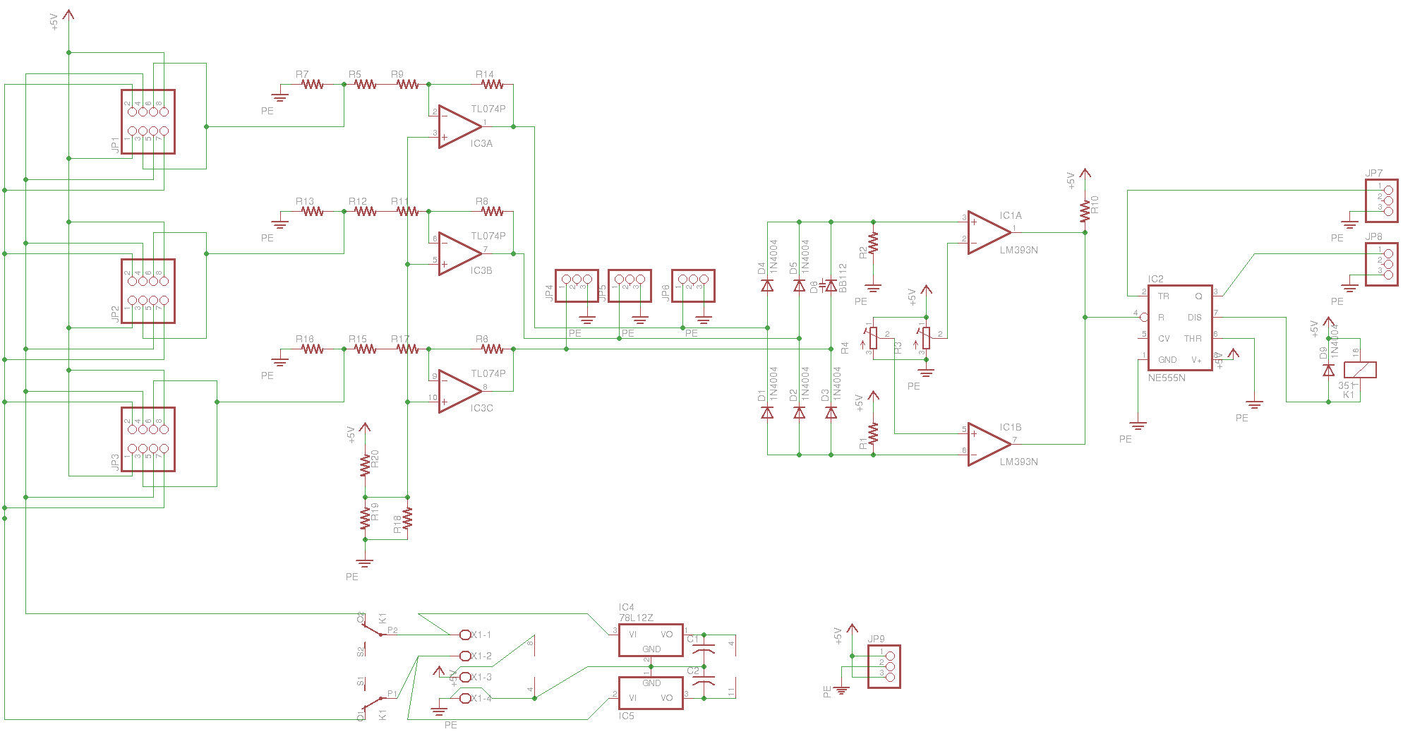
[21:06:31] <rue_school> http://ruemohr.org/~ircjunk/robots/buddy_III/buddy_III_OL.png
[21:07:00] <rue_school> the reason the resistors are paralleled and seriesed like that were to get the right values
[21:07:01] <Lambda_Aurigae> looks awfully complex.
[21:07:06] <Lambda_Aurigae> and where's the arduino?
[21:07:28] * Lambda_Aurigae ducks and runs.
[21:08:21] <rue_school> it takes 3 motors, converts the current from each (-3A to +3A) and scales it to 0-5V, then compares it agianst overload values (+-2.5A) and latches a disconnect relay off if they overload
[21:08:35] <rue_school> the relay controller has a 'alert' output and a 'reset' input
[21:08:42] <rue_school> it is, of course, the 555
[21:09:02] <rue_school> the motors on the robot trip out in groups of 3
[21:09:09] <rue_school> but the current isn't summed for the 3 motors
[21:09:17] <rue_school> if any 1 motor overloads, all 3 are shut down
[21:09:37] <Lambda_Aurigae> nifty design.
[21:09:38] <rue_school> its REALLY sensitive AND fast
[21:09:49] <rue_school> so fast indeed that you cant pwm the motors
[21:09:54] <rue_school> so I have to add a filter to it
[21:09:58] <rue_school> :)
[21:10:28] <rue_school> but, the circuit is there to take the 0.1R current sense resistor and give you a 0-5V reading
[21:10:46] <rue_school> R13 is the 0.1R sense resistor
[21:11:29] <rue_school> anyhow, the information is now yours to pee on as you see fit.
[21:14:04] <tpw_rules> why do you need something that complex?
[21:14:14] <tpw_rules> they're coils of wire, they can take current for a bit
[21:14:32] <rue_school> the mtoors will strip out the gearbox if the motors try
[21:14:47] <rue_school> so its gearbox protection, which is microcontrollerless
[21:15:03] <rue_school> the micro can read the current and reset the breaker, its not involved in it tripping
[21:15:07] <tpw_rules> well my point is what are you doing that you need microcontrollerless protection
[21:15:21] <rue_school> its just stupid to assume that a micro will never lock up
[21:15:34] <tpw_rules> i mean yeah but then what about your pwm solution earlier
[21:15:41] <rue_school> murphys law says it'll happen as soon as you dont want it to
[21:15:54] <rue_school> what pwm?
[21:16:09] <rue_school> oh to protect agianst lockup?
[21:16:18] <tpw_rules> or even the watchdog. control the motors from a timer interrupt which checks if the main loop has touched a variable since the last time it was called. then you can make that small code safe
[21:16:42] <rue_school> I'd just rather that the micro weren't involved
[21:16:53] <rue_school> then there are no bugs
[21:16:55] <tpw_rules> that'll save you from most everything except cosmic rays. set up the hardware watchdog correctly and that's those too
[21:17:08] <rue_school> (less the filter I need to make it work the way I want)
[21:17:17] <tpw_rules> what if your sense resistor starts drifting as it warms up
[21:17:29] <rue_school> well, I'm a guy who protects agianst cosmic rays
[21:17:47] <rue_school> 0.1R shouldn't warm up if I'm not overloading
[21:18:29] <tpw_rules> eh. it just seems overkill and hard to work around. as you mention you can't pwm it
[21:18:58] <tpw_rules> i mean the real issue isn't that the motor is drawing too much current. it's that it's outputting too much torque. and those aren't connected with pwm
[21:19:22] <rue_school> root@fast-laps:/files/programming/c/zippo/ohm# ohm -r 0.1 -p 2
[21:19:22] <rue_school> Wattage is: 2.000000
[21:19:22] <rue_school> Current is: 4.472136
[21:19:22] <rue_school> Voltage is: 0.447214
[21:19:22] <rue_school> Resistance is : 0.100000
[21:19:34] <rue_school> I can use pwm if I filter it
[21:19:39] <rue_school> its just TOO fast right now
[21:19:48] <tpw_rules> is it inductive kickback?
[21:20:06] <tpw_rules> i mean at that point you'll be dissipating a shitton of heat in your fets
[21:20:08] <rue_school> no, its the first pwm pulse trips the overload, just need to average it
[21:20:27] <rue_school> the drivers are bipolar
[21:20:47] <rue_school> its a dual rail drive, I just need two transistors to drive the motors either direction
[21:20:52] <tpw_rules> you'll still be dissipating heat there. if it's averaged half on, then half the power going in is turning to heat
[21:21:08] <tpw_rules> if you pwm it, then the only problems are heat during switching and on resistance
[21:21:17] <rue_school> with 18 motors its easier to use a split supply than to use 72 transistors
[21:22:29] <tpw_rules> get driver chips?
[21:22:53] <rue_school> $$$$
[21:23:00] <rue_school> I already had the transistors
[21:23:01] <tpw_rules> l298n are usually used for steppers but you get two h bridges and you can get a board for them from ebay for like three bucks with heatsink and everything
[21:23:15] <tpw_rules> make sure you don't melt any tho
[21:23:16] <rue_school> L298 suck, have you seen how much voltage they drop?
[21:23:31] <rue_school> HAVE YOU SEEN!?
[21:23:34] <tpw_rules> how much?
[21:23:39] <rue_school> 2V+
[21:23:58] <tpw_rules> have you measured drop with your solution?
[21:24:09] <rue_school> 1v-
[21:24:22] <tpw_rules> yeah. it has two transistors. 2x the voltage drop. it's how any h bridge works
[21:24:27] <rue_school> NO
[21:24:32] <rue_school> it ONLY has two transistors
[21:24:38] <tpw_rules> what
[21:24:40] <rue_school> so only 1x the drop
[21:24:43] <rue_school> split supply
[21:24:46] <rue_school> +-24V
[21:24:48] <tpw_rules> okay that are in the path of motor current
[21:24:55] <tpw_rules> at any given time
[21:24:59] <tpw_rules> unless you are trying to melt the h bridge
[21:25:14] <rue_school> the motor goes to ground, the transistors switch the other side to +- 24
[21:25:18] <tpw_rules> do you have protection for shorting the supplies together btw?
[21:25:20] <rue_school> its not an H bridge
[21:25:30] <tpw_rules> but an l298 is which is why it has 2x the voltage drop
[21:25:33] <rue_school> not in that circuit, but yet
[21:25:41] <rue_school> yea
[21:25:50] <rue_school> thats part of why I used a split supply
[21:25:59] <rue_school> it was cheaper for me too
[21:26:04] <tpw_rules> what even is this project
[21:26:19] <rue_school> the DC-DC to reflect the +24 batteries to -24 is pretty simple
[21:26:24] <rue_school> its a big hexapod
[21:26:40] <tpw_rules> oh. do pneumatics for the next one
[21:27:18] <tpw_rules> wait what gearboxes are needed
[21:27:26] <tpw_rules> or are these big servos with shitty gearboxes
[21:29:35] <rue_school> I'm starting to think I really might be antisocial
[21:29:45] <rue_school> the 12' mecha is pneumatic
[21:29:57] <rue_school> they are vending machine motors
[21:29:57] <tpw_rules> what dimension is 12'?
[21:30:02] <rue_school> height
[21:30:07] <tpw_rules> oh
[21:30:12] <rue_school> to its non-existant head
[21:30:28] <rue_school> look under robots/sparrow1/
[21:30:30] <tpw_rules> put a scope on the base of one of the drive transistors and watch the post-filtered waveform
[21:30:38] <tpw_rules> and keep an eye on the temperature
[21:31:05] <rue_school> the drivers work ok, I'v used them for quite a while with no overloads and just a pathetic supply
[21:31:17] <tpw_rules> i think i'd add capacitors in the monitor circuit rather than on the drive waveform
[21:31:43] <rue_school> the problem is that if I provide for all the motors at say 1.5A, then I need a supply capable of vaporizing any 1 motor
[21:32:00] <rue_school> yea, the current monitor is what gets the filter
[21:32:17] <tpw_rules> oh. i thought you were feeding the transistors with some kind of half-assed sine
[21:32:24] <tpw_rules> so all the heat got dissipated in them
[21:32:24] <rue_school> hahah, no
[21:32:28] <rue_school> nice sharp pwm
[21:32:56] <rue_school> want to help me with a stupid mental block on a school problem?
[21:33:01] <tpw_rules> maaaaae
[21:33:02] <tpw_rules> ybe
[21:33:04] <tpw_rules> damn it
[21:33:09] <tpw_rules> the answer is four
[21:33:18] <rue_school> no, its 42, dont be daft
[21:33:33] <tpw_rules> well this problem is insignificant
[21:33:35] <tpw_rules> so it isn't 42
[21:34:20] <rue_school> ok, you have an inductive load on an ac circuit, you take a 2 channel scope, channel 1 reads voltage, channel 2 reads a current probe, the scope shows a peak of 100V and 10A, (60Hz)
[21:34:31] <rue_school> whats the R and L value?
[21:34:43] <rue_school> oh, right 60 degree phase difference
[21:34:58] <rue_school> I'v DONE this at home and I cant work it out right now
[21:35:12] <tpw_rules> they don't give you a picture of the scopes
[21:35:31] <tpw_rules> about the only think i know is I is behind V by 90 degrees
[21:35:36] <rue_school> yea, you want me to hand-convert it to ascii?
[21:35:51] <rue_school> no, its 60 degrees cause its an RL circuit
[21:37:07] <tpw_rules> i'm just googling. i don't actually know. only just finished high school
[21:37:11] <rue_school> that shut you up cause you know its easy and you cant work it out
[21:37:29] <tpw_rules> not for me
[21:37:39] <rue_school> ah, most schools dont do electronics anymore, so, ok
[21:37:52] <tpw_rules> i got a little electronics. just never into inductance seriously
[21:38:03] <tpw_rules> i know kirck or whatever off's laws ;D
[21:38:09] <tpw_rules> try shorting out the inductor
[21:38:12] <rue_school> did they talk about the imaginary plane?
[21:38:18] <rue_school> sqrt(-1) stuff?
[21:38:21] <tpw_rules> no
[21:38:24] <rue_school> oh
[21:38:31] <tpw_rules> it was more like a pragraph of how an induction motor works
[21:38:47] <tpw_rules> http://www.electronics-tutorials.ws/inductor/ac-inductors.html read here
[21:38:59] <tpw_rules> if it takes as much effort as asciifying then ehc
[21:38:59] <rue_school> well, then I have to assume your self taught on the rest, so I'd say your doing prety good
[21:39:32] <tpw_rules> yeah. i know a decent quantity. just not the basics of electricity, actually
[21:39:36] <rue_school> http://www.electrical4u.com/rl-series-circuit/
[21:39:47] <rue_school> learn it, then teach me ;)
[21:40:01] <rue_school> its a mental block, I'm getting annoyed
[21:40:19] <tpw_rules> i guess you don't get vr and vl?
[21:40:25] <tpw_rules> so you need to intuit it
[21:40:38] <tpw_rules> are they in series?
[21:40:49] <rue_school> there is a typo tho, that diagram shows Vr and Vr ;)
[21:41:02] <tpw_rules> i think i'd only be able to do it if you took a picture of the problem
[21:41:05] <rue_school> yes, its an RL series circuit
[21:41:25] <tpw_rules> oh so R is ohms of the resistor and L is henries
[21:41:42] <rue_school> well, imagine it, you have a 24V transformer hooked up to a 10R resistor in series with a 300mH inductor
[21:42:03] <rue_school> you take a scope, put one channal across the 24V going in
[21:42:05] <tpw_rules> is the resistor 10 ohms?
[21:42:16] <rue_school> no, I'm trying to draw you a mental image
[21:42:18] <tpw_rules> oh no you can't yet
[21:42:25] <rue_school> is this pen working?
[21:42:31] <tpw_rules> a little
[21:42:50] <tpw_rules> isn't it just cranking everything at "series rl circuit analysis" backwards
[21:42:53] * rue_school doodles in the corner of tpw_rules brain to see if there is ink comming out the pen
[21:43:11] <tpw_rules> does it tell you what vr and vl are?
[21:43:12] <rue_school> so, channel 1 looks at the voltage going in,
[21:43:22] <rue_school> and channel 2 is on a current probe
[21:43:47] <rue_school> (this can be done with crafty placing of the scope ground and using the resistor as a current sensor)
[21:43:50] <rue_school> anyhow
[21:43:56] <tpw_rules> 10 = sqrt(R^2 + 2π*60*L)
[21:44:00] <rue_school> there are two sine waves on the scope
[21:44:02] <tpw_rules> that's one equation
[21:44:20] <tpw_rules> we have to know either vr or vl so we can sub
[21:45:09] <tpw_rules> right?
[21:45:17] <tpw_rules> does it show those?
[21:45:34] <rue_school> just a sec, I'm reworking this, cause I realized that working this forward might help me
[21:45:38] <tpw_rules> oh wait. how do you know it's 60 degrees? does it tell you?
[21:45:56] <tpw_rules> then tan(60°) = 2π*60*L/r
[21:46:15] <tpw_rules> yeah, so you just substitute and solve
[21:46:22] <tpw_rules> do you have the answer in the back btw
[21:46:55] <rue_school> this problem I just made up isn't 60
[21:47:54] <tpw_rules> i'm trying to do your original one
[21:47:58] <tpw_rules> did you get that by looking at the scope?
[21:48:17] <tpw_rules> give me a few seconds to boot up my calculator and an answer should be arriving shortly
[21:48:25] <tpw_rules> (maybe)
[21:48:28] <rue_school> Xl = 2Pi*f*L
[21:51:42] <tpw_rules> i get 230mH and 5 ohms
[21:51:49] <tpw_rules> for your original circuit
[21:51:49] <rue_school> ok, did you to rectangular to polar conversions?
[21:51:52] <tpw_rules> no?
[21:51:56] <tpw_rules> is it right
[21:52:03] <rue_school> ah, hmm just a sec
[21:54:11] <tpw_rules> https://i.imgur.com/BNgIPKU.png i used these equations and subbed in what you gave me to solve for what you wanted
[21:54:20] <rue_school> wtf
[21:54:21] <tpw_rules> i only vaguely know how they work, but it seems to have gotten a result
[21:54:43] <tpw_rules> did i get it right
[21:55:07] <rue_school> I have to translate your answer
[21:55:16] <tpw_rules> into what
[21:55:20] <rue_school> power
[21:55:23] <rue_school> but
[21:55:30] <rue_school> ok, you say 5 ohms
[21:55:49] <rue_school> there is 10A peak current, whcih is 7.071A rms
[21:55:58] <tpw_rules> yeah
[21:56:18] <rue_school> 7.07A * 5ohms, is 35.35V
[21:56:43] <tpw_rules> that's what's dissipated across the resistor
[21:56:47] <rue_school> * 7.07A is 249.9 watts
[21:56:51] <rue_school> the answer is 250W
[21:56:57] <tpw_rules> sukkit
[21:56:58] <rue_school> so, yes
[21:57:00] <tpw_rules> :D
[21:57:08] <rue_school> but I missed noticing a step
[21:57:16] <rue_school> which is whats distracting me
[21:57:16] <tpw_rules> lol i couldn't do that for a test tho. i have no idea what those equations mean. i just filled in the letters
[21:57:29] <rue_school> you did fine ;)
[21:57:31] <tpw_rules> what grade are you in or equivalent
[21:58:36] <rue_school> 12 was '95 so, delta 20 so, grade 35
[21:58:55] <tpw_rules> ahh. i thought you were in uni
[21:58:57] <tpw_rules> unless you are going back?
[21:59:04] <rue_school> its tech school
[21:59:20] <tpw_rules> ah.
[22:00:10] <tpw_rules> well good luck on the rest
[22:02:54] <rue_school> hah
[22:02:55] <rue_school> tanks
[22:03:08] <rue_school> ... shall trample your house in the night....
[22:03:22] * rue_school analizes his mental road blocks
[22:13:14] <rue_school> ok, two polar vectors, 50@60 degrees and 12@0degrees, add them
[22:30:25] <rue_school> ooooooh
[22:30:43] <rue_school> ok, at 60degrees, the X will always be half the hyp.
[22:30:50] <rue_school> thats just crazy
[22:33:21] <rue_school> tpw_rules, you misssed a decimal place, its 30mH
[22:33:49] <rue_school> er, 23mH
[22:35:10] <tpw_rules> rue_school: oops. yeah it came out in regular H and i apparently miscounted decimal points
[22:40:06] <rue_school> yea
[22:40:28] <rue_school> but you were perfectly out
[22:40:39] <rue_school> 0 points for that question :)
[22:44:16] <Casper> school?????
[22:45:49] <tpw_rules> rue_school: at least half. i got the resistance right
[23:09:23] <rue_school> heh
[23:09:30] <rue_school> Casper, yea, I'm skooling
[23:10:01] <space_milk> is avr associated with #chan ?
[23:10:07] <space_milk> or are they jsut trolling me?
[23:14:09] <Casper> space_milk: ? a chat room is a channel
[23:14:43] <space_milk> Casper: ?
[23:16:21] <Casper> #avr?
[23:30:45] <rue_school> avr?
[23:45:09] <Casper> I wish there was a kind of mechanical simulator... engine, fuel, pump, alternator, compressor and the like :(
[23:45:46] <Casper> for when my mind get stuck on an "useless" idea