Back
[03:57:49] <Ad0> what is _SFR_IO8() exactly?
[03:57:59] <Ad0> is it a function that returns an address or something
[03:58:07] <Ad0> can it be called once and be used in a variable?
[03:58:14] <twnqx> switch mode power supplies and clamping diodes: what happens if i put ~400µA @ 24V through cmapling diodes into a 3.3V VCC system that has a load of potentially just 10µA? :S
[03:58:41] <twnqx> gut feeling says "smoke"
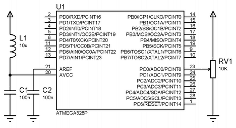
[08:42:45] <Ad0> http://www.embedds.com/wp-content/uploads/2011/05/Atmega328_ADC.png
[08:42:51] <Ad0> won't the filter short?
[08:42:54] <Ad0> it's like zero resistance
[08:54:09] <LeoNerd> Mmm?
[08:55:35] <Ad0> check the left part out
[08:55:48] <Ad0> there's a capacitor and an inductor
[08:56:05] <Ad0> is it because the avcc is grounded too ?
[08:56:19] <Ad0> (aref and avcc connections)
[08:56:34] <Ad0> I got a 10 mH inductor instead of a 1uH one by mistake :-|
[08:56:38] <LeoNerd> AVCC isn't grounded at all
[08:58:30] <Ad0> check the image
[08:58:36] <LeoNerd> Yes. I have done
[08:58:44] <LeoNerd> Are you perhaps confused by the way two lines cross over? They're not joined
[08:58:46] <LeoNerd> There's no dot there
[08:58:53] <Ad0> both are grounded
[08:58:56] <Ad0> through capacitor
[08:59:10] <LeoNerd> That's not grounded then
[08:59:45] <xrlk> idk lmao
[08:59:51] <Ad0> I did this and the vcc of the whole thing dropped to 0.1V
[08:59:52] <xrlk> what does electricity even do
[08:59:59] <Ad0> lol
[09:00:04] <Ad0> so I shorted something for sure
[09:00:07] <LeoNerd> xrlk: I believe it works with magnets.
[09:00:11] <LeoNerd> .. or something
[09:00:14] <LeoNerd> That's half-right...
[09:01:15] <Ad0> wonder what 10 mh does compared to 10 uh
[09:01:43] <Ad0> I was supposed to get a cute axial lead inductor
[09:01:47] <Ad0> and I got this huge radial blonb
[09:01:48] <LeoNerd> Well, presumably has 1000 times more inductance...? ;)
[09:01:49] <Ad0> lol
[09:01:59] <LeoNerd> At a random guess
[09:05:25] <Ad0> http://en.wikipedia.org/wiki/LC_circuit
[09:07:23] <Ad0> the higher the inductance and the lower the capacitance, the narrower the filter bandwidth.
[09:07:31] <Ad0> lol
[09:07:37] <Ad0> I can just drop it then
[09:07:41] <Ad0> I reduced it by a 1000
[09:09:07] <LeoNerd> At this point you're just using it for powerline stability
[09:09:14] <LeoNerd> Having a larger value will just give it more smoothing ability
[09:09:24] <Ad0> don't they just have to match?
[09:09:41] <Ad0> larger coil is nicer signal but why
[09:09:58] <LeoNerd> "match" ?
[09:10:57] <Ad0> yes the inductance vs capacitance
[09:11:15] <Ad0> the example mentions 10uH / 100nF
[09:13:52] <hypermagic> hello my friends :)
[09:13:56] <LeoNerd> Depends on the kind of frequency response you want
[09:14:05] <hypermagic> what's up ?
[09:15:15] <Ad0> I am measuring a temperature sensor
[09:15:22] <Ad0> I am not sure if I even need filtering for that?
[09:21:47] <hypermagic> what is your sensor?
[09:23:15] <hypermagic> twnqx, use a white led as zener diode over vcc? :)
[09:24:33] <twnqx> heh
[09:24:48] <twnqx> nah, i'll look for another way
[09:25:16] <hypermagic> Ad0, the inductance does not matter :) but 100uH is enough there... on that schematic, crossing lines are not connected.
[09:25:20] <twnqx> possibly just fat banks of mosfets / resistors
[09:26:40] <Ad0> hypermagic: yeah
[09:26:44] <hypermagic> twnqx, well white led is about 3V, so you can connect it in parallel with your vcc and you can generate your power using a pullup resistor from some voltage
[09:26:45] <Ad0> it would have a dot if they were
[09:27:12] <twnqx> i don't want to GENERATE power, that's what a LMR14203 will do
[09:27:18] <twnqx> i am worried of excessive power :P
[09:27:59] <twnqx> e.g. 24V through the slamp diodes raising VCC above 3.3V as the current through them exceeds the consumption of the circuit
[09:28:04] <twnqx> clamp*
[09:28:09] <hypermagic> twnqx, i had the same thought with my PA design :) if one would put any voltage to output ports or vcc there were not enough load to pull it below 5V lol, it consumes so little power
[09:28:27] <twnqx> atmega in power-down = few µA
[09:28:41] <hypermagic> i have not tried avalanching the mcu yet, but i assume it will suffer catastrophic breakdown
[09:29:13] <hypermagic> so if you use a device that can take 5V you may use an 5v1 zener or tvs diode without problem
[09:29:17] <twnqx> probably will just drop less efficient LED in
[09:29:38] <hypermagic> but then 5v regulator should not activate it if you are on 5v
[09:29:57] <twnqx> i am powering my 3v3 regulator from the 24V...
[09:30:13] <hypermagic> so you have 5v device? :)
[09:30:16] <twnqx> no
[09:30:18] <twnqx> 3v3
[09:30:20] <hypermagic> ohh
[09:30:30] <twnqx> but i have 24V on my inputs
[09:30:37] <hypermagic> yeah
[09:31:19] <twnqx> maybe i should just use banks of optocouplers :P
[09:31:42] <hypermagic> what is the signal? :P
[09:31:50] <hypermagic> binary?
[09:32:26] <twnqx> yeah
[09:32:32] <twnqx> might use use resistor deviders and be done
[09:32:34] <hypermagic> you can use a bc848 in grounded emitter inverting mode ...
[09:32:37] <twnqx> dividers*
[09:32:41] <hypermagic> that will only pull down
[09:32:50] <twnqx> so?
[09:32:59] <hypermagic> so a resistor in series of base
[09:33:02] <hypermagic> and that's all
[09:33:18] <twnqx> i need ummmm
[09:33:22] <twnqx> 128.
[09:33:24] <hypermagic> activate weak pullup on port
[09:33:27] <hypermagic> hehe
[09:33:30] <twnqx> 128 inputs, 128 outputs
[09:33:59] <hypermagic> then just clam the mcu supply
[09:34:05] <hypermagic> clamp
[09:34:11] <hypermagic> it is well worth the hassle
[09:34:16] <twnqx> they won't go to the cpu directly
[09:34:29] <hypermagic> they will, through your resistor
[09:34:36] <twnqx> inputs go through 74hc244/245
[09:34:37] <hypermagic> and combine the pullup currents
[09:34:45] <hypermagic> oh
[09:34:49] <twnqx> outputs go through 74hc573+uln2003
[09:34:54] <hypermagic> does not mattery anyway
[09:35:18] <hypermagic> you should clamp the ic that is connected to your 24V
[09:35:26] <twnqx> and i need half of the resistors anyway
[09:35:33] <twnqx> as current limiters
[09:35:50] <twnqx> so i can just add the second half to form a divider
[09:36:41] <hypermagic> a divider may be more correct... but a resistor works fine too if it is pulled to ground properly
[09:37:17] <hypermagic> the 3.3V dvice has something like 3.6-3.9V absolute max voltage rating
[09:37:22] <Ad0> I think I fixed it
[09:37:45] <hypermagic> Ad0, i like that mcu too
[09:37:48] <hypermagic> :)
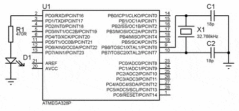
[09:38:07] <hypermagic> i added a 32768Hz xtal from a dead motherboard, and an rgb led for fun
[09:38:27] <hypermagic> made an asynchronous RTC clock with it
[09:38:37] <hypermagic> pretty accurate
[09:38:45] <LeoNerd> And RTC Clock?
[09:38:53] <hypermagic> yes in software
[09:39:01] <twnqx> or short, an rtcc?
[09:39:03] <LeoNerd> .oO( "PIN number", etc etc... )
[09:39:11] <hypermagic> ohh
[09:39:21] <hypermagic> you mean Real Time Clock Clock ;>>
[09:39:45] <Ad0> hehe hypermagic
[09:39:59] <Ad0> I got a crystal too, but forgot why I needed it
[09:40:03] <hypermagic> Ad0, it has internal reference, and a temperature sensor too
[09:40:03] <Ad0> 32768Hz
[09:40:13] <hypermagic> so core temperature can be sensed
[09:40:24] <Ad0> which one?
[09:40:32] <hypermagic> it has only one core :)
[09:41:17] <Ad0> The temperature measurement is based on an on-chip temperature sensor that is coupled to a single ended
[09:41:21] <Ad0> ADC8 channel.
[09:41:21] <hypermagic> Ad0, you got a watch crystal ? then hook it up ;) and you can use it asynchronously for an accurate timer
[09:41:31] <hypermagic> Ad0, yes
[09:41:34] <Ad0> I have a bunch of 32768Hz
[09:42:04] <hypermagic> so device can run internal 8MHz for example while having a 32768Hz clock too
[09:42:17] <Ad0> yeah
[09:42:24] <Ad0> I saw a schematic where the crystal was used
[09:42:28] <Ad0> but I forgot where it is
[09:42:32] <Ad0> I think it was in the datasheet
[09:42:34] <Ad0> for good ADC
[09:42:40] <hypermagic> you connect it as any other crystal
[09:42:52] <hypermagic> you just need to set the fuse bits accordingly
[09:43:00] <hypermagic> or your cpu will run a bit slow ;)
[09:43:23] <Ad0> I am shit scared of fuse bits
[09:44:17] <Ad0> oh yeah now I remember
[09:44:21] <Ad0> it was for power save mode
[09:44:55] <Ad0> http://www.embedds.com/wp-content/uploads/2010/12/AVR_RTC_anim.gif
[09:45:10] <hypermagic> http://www.engbedded.com/fusecalc/
[09:45:28] <Ad0> I use atmel studio
[09:45:30] <hypermagic> well... if you are lazy to calc them
[09:46:07] <Ad0> hehe
[09:46:13] <hypermagic> hm i think those 18pf caps are too large.
[09:46:16] <Ad0> I use uart to print out the temp to a terminal on my computer :)
[09:46:27] <hypermagic> the 32768Hz ones take about 2x8pf
[09:46:46] <hypermagic> i used none, since my avr pins are a few pf and i thought it will be fine.
[09:47:41] <Ad0> there is recommended designs
[09:48:42] <hypermagic> if the xtal is 12.5pf load capacitor rated then you can change the frequency a few ppm by changing them
[09:49:07] <hypermagic> using 5-20pf for example
[09:49:53] <hypermagic> it will only become non optimal for the xtal
[09:50:39] <hypermagic> if you need more accurate time like your clock drifts 1-2s / day you can correct it in software too
[09:50:50] <Ad0> imagine the guy who wrote the datasheet
[09:50:50] <Ad0> lol
[09:50:51] <hypermagic> the frequency will by just off, but stable
[09:50:54] <Ad0> 300 pages
[09:52:11] <hypermagic> so what is your temperature sensor?
[09:52:19] <hypermagic> what are you sending with? a diode?
[09:52:28] <hypermagic> *sensing
[09:53:01] <Ad0> a nice little chip that doesn't draw shit
[09:53:04] <hypermagic> an RC lowpass filter can improve the result if thre is a noisy environment and longer cable
[09:53:05] <Ad0> NJ 28
[09:53:29] <hypermagic> plan B is to apply digital filtering
[09:53:32] <Ad0> http://www.avx.com/docs/masterpubs/ntctherm.pdf
[09:53:44] <twnqx> i never thopught i'd study data sheets to find inefficient LEDs
[09:53:52] <Ad0> the reading is pretty damn stable now
[09:54:07] <hypermagic> that is not a chip m8, that is a temperature dependent resistor ;)
[09:54:35] <Ad0> " Coated chip with phenolic Coated chip with epoxy Chip
[09:54:35] <Ad0> resin + varnish Coated chip with epoxy AWG30 insulated leads
[09:54:36] <Ad0> + tinned copper wires
[09:54:50] <Ad0> it acts as a thermistor
[09:54:54] <Ad0> but I guess it's a small chip?=
[09:55:05] <hypermagic> hm. ok... chip as in cornflakes
[09:55:08] <Ad0> lol
[09:55:13] <Ad0> yeah summat
[09:55:19] <hypermagic> i thought some microchip that has a computer
[09:55:29] <hypermagic> there are digital temp sensors
[09:55:34] <Ad0> yeah
[09:55:37] <Ad0> almost the same size
[09:55:41] <Ad0> a bit bigger
[09:55:43] <hypermagic> sot23-6
[09:55:49] <hypermagic> or sc70 ?
[09:56:02] <hypermagic> sot-373
[09:56:05] <Ad0> ds18B20+
[09:56:11] <Ad0> that's the classic one
[09:56:24] <hypermagic> i like the ntc or diode approach.
[09:56:45] <hypermagic> you can get an RTD if you want higher accuracy, temperature
[09:57:36] <hypermagic> Ad0, i need to code an ntc handler too now
[09:57:48] <Ad0> hehe
[09:58:03] <hypermagic> the simplest way is to make a 2 point calibration and linear interpolate it
[09:58:11] <hypermagic> it will have to be stored in eeprom
[09:58:13] <Ad0> it is much cheaper and better than the stupid ds18B20+
[09:58:19] <hypermagic> 2 endpoints with 2 temperature values
[09:58:22] <Ad0> it was a PITA to work
[09:58:43] <Ad0> ok
[09:58:47] <hypermagic> only problem is to make simple to use for users
[09:59:16] <hypermagic> and if 7 segment display is present, it can not display all letters
[09:59:29] <hypermagic> so not very informative
[10:01:25] <Ad0> hehe
[10:01:29] <Ad0> take a pic!
[10:01:52] <hypermagic> what pic?
[10:02:01] <hypermagic> we don't use pic
[10:05:46] <Ad0> a picture
[10:05:50] <hypermagic> ohh
[10:05:58] <hypermagic> i only have a test setup
[10:06:17] <hypermagic> looks like some bomb from a movie
[10:07:37] <hypermagic> i have a 7 segment panel from a printer i think, i hacked the board and added soic HC type gates instead of the dip ttl ics and soldered an ide connector at the edge, and i connected it to my atmega board with an 80line ide cable ^^
[10:07:52] <hypermagic> it also have some buttons
[10:08:06] <xrlk> has any1 taken an atx psu and changed it 2 benchtop
[10:08:32] <hypermagic> i have a server supply here that i use for power
[10:08:44] <hypermagic> but i have not changed its operation
[10:08:53] <hypermagic> 3v3, 5v, 12v
[10:08:53] <xrlk> ok
[10:09:06] <hypermagic> 550w redundant :)
[10:09:16] <hypermagic> enough to power some atmegas
[10:10:02] <hypermagic> but you could take an old at/atx supply and make a variable psu from it withan avr, or arm
[10:10:33] <hypermagic> i thought of this too, only concern about this is if the mcu hangs, or delays, the output voltage/current can go wild
[10:11:00] <hypermagic> it would be even possible to take out the tl494 ic and replace the functionality with an avr
[10:11:23] <hypermagic> but a few us fault in timing then would result in exploding primary transistors
[10:11:39] <hypermagic> and fault in regulation would result in output overvoltage/current
[10:12:21] <hypermagic> fault can be triggered by hardware, or software errors, depends partially on the stability of your software
[10:12:34] <hypermagic> otherwise it sounds nice project
[10:13:44] <hypermagic> xrlk, what is your opinion about the stability/reliability of avrs ?
[10:14:17] <hypermagic> avrs don't have dac, but pwm could be generated for analog controlling tl494 too...
[10:15:13] <hypermagic> an atx would be the best with 5Vstby functionality ;)
[10:16:05] <Ad0> hehe
[10:16:19] <Ad0> i am doing low power aa battery atuff
[10:16:24] <LeoNerd> Beware that ATX supplies often have /minimum/ current requirements
[10:16:30] <LeoNerd> SMPSes don't like being underloaded
[10:16:54] <Ad0> avrs cant output analog signals?
[10:17:08] <LeoNerd> Depends how you mean "output" and "analog"
[10:17:19] <Ad0> dac
[10:17:22] <LeoNerd> If you only want a low-frequency thing, you could use a high-speed PWM + RC filter
[10:17:30] <LeoNerd> You could use a DAC attached over SPI/I2C
[10:17:42] <Ad0> yeah
[10:17:56] <LeoNerd> I do find it slightly odd that they don't have DACs built in though, because the ADC itself for example needs a DAC to function
[10:18:01] <Ad0> i mean if you wanyed to make a synth
[10:18:05] <LeoNerd> So it would have been easy enough just to provide another one surely?
[10:18:35] <hypermagic> LeoNerd, that is only because the output 5V and 12V is sensed combined, if i reconnect the sensing circuit to only sense 12V side then no problems
[10:18:45] <Ad0> i need to find a cheap gpio gps
[10:18:54] <LeoNerd> hypermagic: Mmm?
[10:19:00] <xrlk> yea hackvana
[10:19:02] <xrlk> hypermagic,
[10:19:04] <hypermagic> but one must make sure that the tl494 gets its minimum working voltage for normal operation
[10:19:05] <LeoNerd> I mean, in general: An underloaded SMPS may well output overvoltage
[10:19:16] <xrlk> i wouldn't see the atx psu being too useful
[10:19:42] <hypermagic> well my server supply is loaded by the fan and it is enough for it...
[10:19:52] <hypermagic> it regulates well
[10:20:05] <xrlk> brb
[10:20:43] <Ad0> i have a small 3.3v voltage regulator
[10:20:46] <hypermagic> for a badly designed/cheap voltage mode psu, if you use it with very light load, and load it with 8A for example, it will ramp up the pwm so high it will not be able to reduce it when you instantly take it off
[10:20:53] <Ad0> on a 5v supply
[10:20:59] <hypermagic> so it will destroy things on the output instead
[10:21:27] <hypermagic> but this could be improved by adding some more puffer capacitors, and maybe a hdd to load a bit
[10:21:34] <hypermagic> (or resistor)
[10:21:56] <hypermagic> LeoNerd, this is basically how it works
[10:22:49] <hypermagic> also if the 5V and 12V lines are sensed together, like in old at supplies, and cheap atx supplies, if you load the 5V line, 12V line will rise
[10:23:28] <hypermagic> but they should be well coupled...
[10:23:57] <hypermagic> time flies ...
[10:24:14] <LeoNerd> like an arrow
[10:24:42] <hypermagic> LeoNerd, the problem with filter loop controlling power supply is, you make a short circuit, it will blow up before you can take it down
[10:24:57] * LeoNerd nod
[10:25:06] <hypermagic> though a diode could be added for pull-down maybe
[10:25:11] <hypermagic> :/
[10:25:36] <hypermagic> or shorting the capacitor with an n-fet :)
[10:25:46] <hypermagic> that should turn off the output fast
[10:26:01] <hypermagic> i'll think about that
[10:27:21] <hypermagic> but it does not change the fact that if you filter your pwm it will slow control loop down
[10:27:43] <hypermagic> a dac would be much better in this aspect
[10:28:19] <hypermagic> but if i had to attach an spi dac i would use pwm instead...
[10:28:43] <LeoNerd> Just get a SPI DAC then
[10:29:00] <hypermagic> overcomlicates things and additional cost i think
[10:30:14] <hypermagic> btw why don't avrs contain dacs ?
[10:30:23] <hypermagic> it would be nice to have 3-4 dacs at least
[10:30:44] <hypermagic> with 3 dacs we could output rgb image to a lcd monitor
[10:31:25] <hypermagic> (ok well, with only fast dac)
[10:37:14] <twnqx> ... actually i have an even better reason to use a resistor divider. my input is 24V or *open*
[10:40:14] <hypermagic> :)
[10:40:27] <hypermagic> you can divide it down to 3.3V then
[10:40:50] <hypermagic> and you already have the pulldown resistor too, though pulldown is not a good option for mcu
[10:40:58] <hypermagic> but you used a buffer that is inverting?
[11:45:42] <hypermagic> do you think an optical communication would work by multiplexing polar filtered signals and sending over a single link ?
[11:46:26] <LeoNerd> I think some of them already do, don't they?
[11:46:59] <hypermagic> i don't know any yet, but there are polarization filters n optical drives too
[11:47:21] <hypermagic> reflections change polarization too
[11:47:22] <LeoNerd> Perhaps finally a useful task for a peacock mantis shrimp
[11:47:48] <hypermagic> what do you mean by that ? :)
[11:48:04] <LeoNerd> They have polarisation-sensitive eyesight
[11:48:08] <hypermagic> because its good eyes ?
[11:48:10] <LeoNerd> So they'd be able to help read it
[11:48:11] <hypermagic> :)
[11:48:17] <hypermagic> hhaha
[11:48:22] <LeoNerd> They rotate their eyes to detect the polarisation
[11:48:39] <hypermagic> let's make a polar datacom then name it "peacock mantis shrimp" then
[11:49:02] <hypermagic> i have a better idea
[11:49:18] <LeoNerd> The most amusing thing I find about these animals is that they are not peacocks, they are not mantises, and they are not shrimp.
[11:49:24] <hypermagic> i'd use multiple sensors each with rotated polar filters
[11:50:24] <hypermagic> but the peacock mantis shrimp probably does not emit polarised light as binary data for comunicating with other peacock mantis shrimp
[11:50:27] <hypermagic> :)
[11:50:38] <LeoNerd> Ah.. true
[11:50:50] <LeoNerd> Yeah, it's just a receiver. So you'd need something else to transmit
[11:51:58] <twnqx> ffs
[11:52:00] <hypermagic> will the peacock mantis shrimp get dizzy if i show it circular polarised light? :)
[11:52:10] <twnqx> a sidenote just broke my design plan :(
[11:52:21] <twnqx> my do the ULN* leak 50µA...
[11:52:25] <twnqx> why*
[11:52:32] <hypermagic> turn it off
[11:52:40] <twnqx> IN OFF STATE
[11:52:44] <hypermagic> oh
[11:52:55] <hypermagic> then there is a resistor divider like in the 7555
[11:53:12] <hypermagic> to forbid you using it forever with a battery
[11:53:17] <twnqx> or maybe i read that wrong
[11:53:39] <twnqx> here it says off-state INPUT current
[11:54:21] <hypermagic> sounds like an input pulldown resistor
[11:54:32] <twnqx> Iout_off (Typ) (uA) sounds like output to me
[11:54:36] <hypermagic> in case you feed it with a tristate buffer
[11:55:03] <hypermagic> iout ?
[11:55:38] <hypermagic> http://www.imaginationhealer.com/peacock-mantis-shrimp.html haha haha
[11:55:42] <hypermagic> so colorful
[11:55:44] <twnqx> yeah, idgi
[11:55:49] <hypermagic> this thing knows about light
[11:57:37] <twnqx> meh
[11:57:41] <hypermagic> They kill their prey by hitting them with a very fast claw. So fast, it cracks the shell of the animal, breaks the barrier of sound -- so they are ninja too
[11:57:44] * twnqx checks price of 200 mosfets
[11:57:53] <LeoNerd> Yeah, they're crazy
[11:58:02] <hypermagic> twnqx, $5 ?
[11:58:23] <hypermagic> try 2n7002 ;)
[11:58:38] <twnqx> need smaller than sot-23
[11:58:54] <LeoNerd> -smaller- than SOT-23?
[11:59:35] <hypermagic> twnqx, meet your new friend 2N7002DW H6327 (INF) DUAL N-FET 60V 0.3A 0.5W Rds<4R SOT-363
[11:59:44] <hypermagic> :)
[11:59:51] <twnqx> 60V sounds good
[11:59:54] <hypermagic> now you only need 100 doubles
[12:00:02] <twnqx> doubles?
[12:00:06] <twnqx> oh
[12:00:08] <hypermagic> check the ds :)
[12:00:40] <twnqx> ugh, the routing is a nightmare though
[12:02:41] <hypermagic> not that bad, and you already have resistors anyway
[12:03:11] <twnqx> i have no resistors on the outputs anywhere :P
[12:04:03] <twnqx> 60V Vdss is good
[12:04:38] <twnqx> no idea what my target will sink though
[12:05:02] <twnqx> i only know it has a 200k input resistor
[12:06:27] <hypermagic> gates...
[12:06:45] <hypermagic> you probably want resistors on gates no?
[12:07:24] <hypermagic> they serve as simple bridges :P
[12:07:25] <twnqx> on bill gates?
[12:07:25] <twnqx> _>
[12:07:27] <twnqx> :>
[12:07:44] <twnqx> 100 of them fairchilds are 22€...
[12:08:30] <hypermagic> 100 should be around $6
[12:08:45] <twnqx> 17€ from infineon
[12:08:50] <twnqx> where are you buying?
[12:10:36] <hypermagic> from hungary
[12:10:41] <hypermagic> but check out tme then
[12:10:43] <hypermagic> http://www.tme.eu/en/details/2n7002ps/multi-channel-transistors/nxp/#
[12:13:36] <twnqx> 100 pcs - 19€
[12:13:44] <twnqx> oh, 19$
[12:13:50] <twnqx> but about the same as digikey, then
[12:16:55] <hypermagic> twnqx, or you'd like these more?
http://uk.farnell.com/webapp/wcs/stores/servlet/Search?catalogId=15001&langId=44&storeId=10151&categoryId=700000004648&st=transistor%20array&pageSize=25&showResults=true&pf=110204108
[12:17:35] <hypermagic> http://www.farnell.com/datasheets/89933.pdf this also has resistors haha
[12:19:34] <twnqx> the input current is not a problem
[12:21:16] <twnqx> i think it's the clamp diode's reverse leakage current that's my problem
[12:21:21] <twnqx> output clamp diode, that is
[12:22:55] <hypermagic> http://uk.farnell.com/texas-instruments/uln2003adr/transistor-array-npn-smd/dp/1470513
[12:23:02] <hypermagic> this is the cheapest ;>
[12:24:14] <hypermagic> 250 (Cut Tape 1470513) x 0.156 = £39.00
[12:24:53] <hypermagic> 7 transistors each
[12:29:22] <hypermagic> i don't know what are you doing now
[12:29:36] <hypermagic> but you can use a 4148 with glass package for light sensing
[12:30:03] <hypermagic> it can be lol to discover this if you use them for signal clamping ;)
[12:30:25] <hypermagic> also leds generate current if you give them light
[12:46:26] <hypermagic> would you choose 4pin or 6 pin rgb led? :/
[12:46:33] <hypermagic> 4pin are cheaper
[12:46:42] <hypermagic> (half price)
[12:55:31] <hypermagic> what kind of voltage regulation you prefer for your projects?
[12:56:12] <hypermagic> primarily 3.3V with an ldo ?
[13:04:44] <fractallife> twnqx, this part is awesome to route too
http://www.tme.eu/en/Document/e02cd0efe18f56099c95ffcaea6e0523/2N7002PS.pdf
[13:04:47] <fractallife> just checked out the ds
[13:13:22] <fractallife> freenode died
[13:15:18] <specing_> RIP