Back
[02:55:27] <Ad0`> hello
[02:56:40] <vino> hi
[03:01:44] <Ad0> :)
[03:08:55] <Ad0> how do you specify 8 MHz when running 16 MHz crystal?
[03:20:17] <Fleck> Ad0?
[03:20:59] <Fleck> you can set fuses to use internal clock, if that works at 8MHz
[03:24:12] <Ad0> maybe I'll do that so I can lose the whole crystal
[03:24:32] <Ad0> I did crystal with clockdiv / 8
[03:24:35] <Ad0> so I have 2 mhz now
[03:25:12] <Ad0> Fleck: is there an issue with the ISP programmer being connected while I use SPI and USART?
[03:25:25] <Ad0> or can it remain connected, or do I have to program in one spot and just move the chip over?
[03:26:21] <Fleck> I usually leave it connected
[03:26:49] <Fleck> but if SPI lines have low resistance, it may be a problem!
[03:27:58] <Ad0> ok
[03:28:19] <Ad0> it would be a problem programming then
[03:37:03] <Fleck> right Ad0
[04:37:27] <Ad0> Fleck: the programmer or something seems to reset the chip constantly
[04:42:11] <Fleck> programmers don't do that if not used... usually
[04:45:12] <Ad0> hm...
[04:45:19] <Ad0> well now I managed to do the ultimate newbie mistake
[04:45:35] <Ad0> enabling RSTDISBL by mistake
[04:45:42] <Ad0> I guess I just have to buy another one
[04:47:16] <Fleck> depends on tools/stuff available around you ... :D
[04:47:55] <Ad0> I got the avrisp programmer
[04:49:59] <Fleck> thats it? :D
[04:50:25] <Fleck> you need HVSP/HVPP (depends on chip you use) to reset fuses now
[04:50:38] <Fleck> you can make one with avr :D
[04:54:07] <Ad0> well I got the attiny45 left...
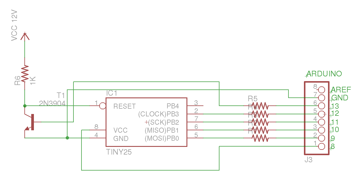
[04:57:09] <Fleck> http://www.rickety.us/2010/03/arduino-avr-high-voltage-serial-programmer/
[04:57:18] <Ad0> yeah just read it
[04:57:27] <Ad0> but to order all that I will just order a bunch of new chips instead
[04:57:27] <Ad0> :P
[04:58:58] <Fleck> a made this once :D worked! :p now I have miniprog (TL866A) though
[04:59:49] <Fleck> all that? means what?
[05:00:01] <Ad0> hehe
[05:00:05] <Ad0> the shield etc
[05:00:05] <Fleck> you need few resistors and transistor...
[05:00:08] <Fleck> naah
[05:00:12] <Fleck> don't need that
[05:00:23] <Ad0> well I don't even have a transistor so it takes me the same time to order
[05:00:36] <Ad0> anyway I have a bunch of resistors
[05:00:37] <Fleck> no spare parts around? :D
[05:00:43] <Ad0> an old mainboard :P
[05:00:59] <Fleck> you can get transistor there :D
[05:01:13] <Fleck> but ok, you should know better
[05:02:23] <Ad0> now I do hehe
[05:02:28] <Ad0> but I need to order some crap anyway
[05:02:41] <Ad0> like the ATMEL-ICE Basic Kit
[05:04:00] <Ad0> AT91SAM-ICE JTAG Emulator
[05:04:08] <Ad0> what does that do ? just emulate the whole chip ?
[05:12:50] <Ad0> ATTINY48-PU is nice
[05:56:03] <Ad0> http://www.rickety.us/wp-content/uploads/2010/03/diagram.png
[05:58:01] <Fleck> ?
[06:08:14] <Ad0> hehe
[06:08:17] <Ad0> BTLC1000
[06:08:21] <Ad0> wonder when that's out
[06:10:14] <Ad0> http://www.ebay.co.uk/itm/HM-10-CC2541-CC2540-BLE-4-0-Bluetooth-UART-Transceiver-Module-Central-Genuine-/291417806051?pt=LH_DefaultDomain_3&hash=item43d9dad4e3
[06:10:17] <Ad0> that's annoying.
[06:10:26] <Ad0> those pinouts are annoying
[06:15:51] <Ad0> to convert 5 V logic signals to 3V, is it enough to just use voltage regulators?
[06:16:10] <Ad0> are are they too slow or something ?
[06:17:34] <Lambda_Aurigae> don't use a voltage regulator...
[06:17:50] <Lambda_Aurigae> zener diode or a level translator or some such.
[06:18:16] <Ad0> ok
[06:18:38] <Lambda_Aurigae> some devices that operate at 3V can accept 5V level inputs too...not all of them though.
[06:20:35] <Ad0> the solution is to use low clock attiny and keep everything at 3.3V
[06:20:48] <Ad0> methinks
[06:27:44] <Lambda_Aurigae> talking to an NRF module?
[06:28:08] <Lambda_Aurigae> or,,,,bluetooth.
[06:28:14] <Lambda_Aurigae> just scrolled up.
[06:28:53] <Ad0> that HM10 module
[06:29:04] <Ad0> I ordered 3
[06:29:07] <Lambda_Aurigae> http://lea.hamradio.si/~s57uuu/uuusb/
[06:29:12] <Lambda_Aurigae> about halfway downt he page.
[06:29:14] <Ad0> but I am gonna run it at 3.3V the whole thing
[06:29:26] <Lambda_Aurigae> simple way to convert from 5V to 3.3V with 2 resistors.
[06:30:01] <Lambda_Aurigae> now, 3.3V to 5V is a bit more difficult,,,,BUT!!!!,,,usually you don't need to.
[06:30:22] <Lambda_Aurigae> 5V devices will mostly accept 3.3V logic high unchanged.
[06:31:01] <Ad0> yeah
[06:31:13] <Ad0> and as I mentioned, I will power the whole thing at 3.3V
[06:31:26] <Ad0> I have a 5V supply and a 3.3V regulator
[06:31:29] <Lambda_Aurigae> a 10K and 15K resistor in a voltage divider setup works perfect.
[06:31:45] <Ad0> yeah that also works, but for the other way ?
[06:31:57] <Ad0> you need something that ups the 3.3V to 5V
[06:32:05] <Lambda_Aurigae> nope.
[06:32:15] <Lambda_Aurigae> not if you are using an attiny at 5V
[06:32:23] <Lambda_Aurigae> they will accept 3.3V high as a logic high.
[06:32:28] <Ad0> cool
[06:32:36] <Ad0> I will use it at 3.3V so NP
[06:32:41] <Ad0> I mean why go 5V at all ?
[06:34:47] <Lambda_Aurigae> https://learn.sparkfun.com/tutorials/logic-levels they explain it rather well here.
[06:35:13] <Lambda_Aurigae> as for why go 5V over 3.3V? sometimes speed of chips
[06:35:17] <Lambda_Aurigae> sometimes ease of use.
[06:36:46] <Ad0> it's gonna be a low power battery powered solution
[06:36:58] <Ad0> so I figured an attiny picopower
[06:37:04] <Ad0> together with HM10
[06:37:08] <Ad0> running @ 3.3V
[06:42:10] <Ad0> https://youtu.be/CvFZSA_QD2g
[07:54:31] <LeoNerd> Wow... I never thought I'd see one of these. An I2C device (MCP2309) which uses a single ADDR pin to encode 3 address bits, by using a flash-ADC and using a voltage divider on the input
[07:58:19] <Ad0> hehe
[07:58:46] <Ad0> sometimes it doesn't seem like they wanna sell their products, slowass bastards
[07:59:24] <LeoNerd> Oh it's a nice idea. The chip comes in SPI or I2C forms
[07:59:44] <Ad0> MCP2309 =?
[07:59:49] <LeoNerd> So the pin that's SS on the SPI form, is this single ADDR pin on I2C. It makes for an easy swap of parts; all the other pins are the same
[08:00:01] <LeoNerd> 2309 is I2C, 23S09 is SPI
[08:00:23] <Ad0> what chip is this?
[08:00:25] <LeoNerd> I'm already talking to an SPI chip, so an SPI based expander would be nicer for me than I2C. Basically, I've just run out of IO pins on my board
[08:00:55] <LeoNerd> I think my current plan though is just to move all my output LEDs to a shift register, and talk SPI to that; then I can reduce my current set of 4 LED output pins down to a single one, being the SS line of that
[08:01:23] <Ad0> https://www.nordicsemi.com/eng/Products/Bluetooth-Smart-Bluetooth-low-energy/nRF51822
[08:01:27] <Ad0> seen this one ?
[08:01:43] <Ad0> wonder how much more efficient that is versus an attiny + a HM10
[08:01:58] <LeoNerd> I've not looked into BT/BLE at all
[08:02:08] <Ad0> the nordic has a full SoC
[08:02:16] <Ad0> that is, an ARM cortex with IO pins etc
[08:02:19] <Ad0> + full BLE stack
[08:02:26] <Ad0> it HAS to be more efficient
[08:02:41] <LeoNerd> Man this chip is nice.. sooo much nicer than just using an SR for GPIO expansion
[08:02:45] <Ad0> I phoned them up and they just directed me to the dev zone, didn't bother answering a simple question I had
[08:03:08] <LeoNerd> Individual control of pullup per output pin, polarity per input pin, very flexible control of interrupt on pin change...
[08:03:41] <LeoNerd> It even has an input capture latch, so the moment a pinchange occurs it will latch the value, so you can see short spikes even if the real pin value changed by the time you read it
[08:07:39] <Ad0> ncool
[08:08:33] <LeoNerd> Huhhhhman this is a weeeeird chip
[08:09:10] <LeoNerd> The first byte over SPI still looks like an I2C-like control byte, with address and read/write direction. The SPI version of the chip still has address pins. It *still* checks if the address in the first byte matches the hardware address
[08:09:19] <LeoNerd> .... whhhhyyyy would an SPI device have addressing logic?
[08:10:49] <Ad0> good for you, I just bricked my avr
[08:11:18] <Ad0> the damn thing was resetting constantly, probably triggering the programmer through the same SPI ports
[08:11:26] <Ad0> something was happening
[08:11:38] <Ad0> so it seems like I have to disconnect the programmer to make it run properly
[08:19:02] <vino> bye..
[08:26:49] <LeoNerd> Anyone know of a decent SPI-attached UART?
[08:28:56] <fieldman> i have a drawer full of expander chips !
[08:29:03] <Ad0> you mean like an SPI to UART adapter sorta?
[08:32:06] <fieldman> well the good news is dudes i get to make a gadget today
[08:33:18] <LeoNerd> Ad0: Yes; I want a second UART, and I have the SPI port nicely spare. So I want to talk SPI to an external UART
[08:33:53] <LeoNerd> Preferrably one with a nice big buffer in it. Ideally big enough to store an entire DMX512 frame, of (annoyingly) 513 bytes long
[08:34:20] <LeoNerd> Failing that I suppose I could write myself a DMX offload chip on a 'tiny84 or such
[08:34:35] <Ad0> hehe
[08:34:37] <Ad0> not 512
[08:34:40] <Ad0> what a shame
[08:34:41] <Ad0> :D
[08:34:43] <fieldman> maxim makes a chip for that i think
[08:35:03] <Ad0> if I choose to power at 2.5V, is there a nice component that will up the voltage to 3.3V?
[08:35:10] <LeoNerd> Yah.. it's super-annoying. The DMX frame format is one command byte then the data. So there's a command byte to say "here's channel data", followed by the data for 512 channels
[08:35:28] <Ad0> DMX? lightning controls?
[08:35:43] <LeoNerd> Yah
[08:35:46] <fieldman> lol @ 513
[08:35:47] <twnqx> there are many level shifters
[08:35:49] <fieldman> thats weird
[09:02:33] <malinus> Ad0: I'm not sure it's possbile (to brick your avr). Unless the word brick means somethink else than what it used to :).
[09:03:45] <LeoNerd> It's impossible to brick an AVR chip by purely software means (other than actual physical hardware damage, such as trying to force-drive a grounded output pin)
[09:03:50] <Ad0> malinus: setting the disable reset to "On" bricks it unless you have a high voltage
[09:03:58] <Ad0> programmer
[09:04:05] <LeoNerd> However, you might end up sticking it in such a weird combination of fuses that it needs HV(S/P)P to recover it
[09:04:53] <malinus> yeah the good old "let's disable reset to because I need another pin" :D
[09:05:07] <malinus> -to
[09:05:41] <LeoNerd> It's why I built my HVSP programmer :)
[09:05:51] <LeoNerd> Getting 6 GPIO pins on a tiny85 makes a lot of difference as compared 5.
[09:05:58] <LeoNerd> Similarly, 12 vs. 11 on a tiny84
[09:06:12] <LeoNerd> Bigger than that it tends not to make such a big difference any more
[09:06:53] <malinus> 6PIN avr doesn't make a lot of sense. If you need a small footprint, why pick a DIP in the first place?
[09:07:13] <malinus> well you can get them in smd flavour, but still.
[09:07:16] <LeoNerd> Who says I'm using DIP?
[09:15:54] <Ad0> that 1 wire shit is some lame ass crap
[09:19:23] <LeoNerd> 1wire is.... interesting
[09:19:41] <LeoNerd> The bus enumeration protocol is particularly amusing
[09:20:43] <Ad0> yeah
[09:20:49] <Ad0> but if you want to read only one temp
[09:20:56] <Ad0> isn't a thermistor with ADC better?
[09:21:01] <Ad0> and less power consuming
[09:21:18] <LeoNerd> If you just want a single one maybe you want something I2C-connected?
[09:21:26] <LeoNerd> The 1wire ones are more useful for having a bus of many
[09:21:40] <LeoNerd> Though if you know you have only one thing connected you can use the SKIP_ROM command and just read it directly
[09:22:03] <Ad0> I guess that would consume less...
[09:24:59] <LeoNerd> I'm not sure... they are supposed to be fairly low-power anyway
[09:28:50] <LeoNerd> Meh...
[09:29:00] <LeoNerd> I think there are literally no decent SPI-based GPIO expanders anywhere
[09:29:37] <LeoNerd> There are lots of interesting I2C-based ones, and the rare few SPI ones I can find are literally just an SPI interface bolted on top of that
[09:30:06] <LeoNerd> So they still all have a basic idea that a single bus transaction is a read *or* a write operation; so e.g. I can't write out a new output value while simultaneously reading in the old one... for example
[09:34:12] <Ad0> hehe
[09:34:15] <Ad0> what is the standard diode
[09:35:25] <LeoNerd> ?
[09:35:59] <Ad0> just a normal diode
[09:36:01] <Ad0> ya know
[09:36:03] <LeoNerd> 1N4001 for rectification (up to about 1A); 1N4148 for signals seems fairly common/popular
[09:36:07] <Ad0> there are like 809409184091284 different variants
[09:36:13] <Ad0> thanks
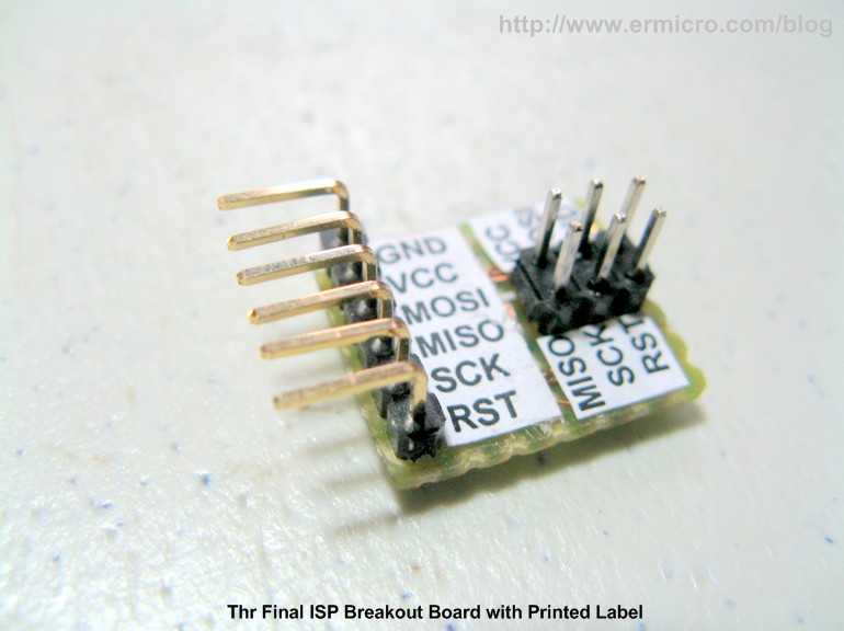
[09:57:28] <Ad0> any ide where I get a 6 pin connector for the AVRISP to nicely insert it into a breadboard?
[09:57:31] <Ad0> idea
[09:57:38] <Ad0> a 6 pin connector of some sort
[09:57:46] <Ad0> so I can easily disconnect
[09:59:32] <Ad0> like a long SIL header that can be bent
[10:01:54] <LeoNerd> I just made myself a tiny 1x6 to 2x3 adapter board
[10:02:11] <LeoNerd> Tindie also has a few of various kinds you can buy.. ideally you'd have one with nicely labeled pins on the 1x6 side so you know what they are
[10:02:30] <LeoNerd> That also said; most of my dev work on breadboards I tend to use chip holders that already have ISP6 headers on them :)
[10:06:11] <Ad0> http://docs-europe.electrocomponents.com/webdocs/1388/0900766b8138872c.pdf
[10:06:35] <Ad0> is this what's normally used=
[10:06:55] <Ad0> I guess I can't bend this one
[10:10:24] <Ad0> http://www.ermicro.com/blog/wp-content/uploads/2013/02/ISP_Breakout_01.jpg
[10:12:28] <woddy> hey
[10:12:33] <woddy> anyone still remembers AVR Studio 4?
[10:15:51] <woddy> I'm using AVR Simulator for AVR128 @AVR Studio 4.19 in the "Processor" window, I can only have my registres shown in hexadecimal or in decimal, not in binary, thats a bit of a pain in the ass
[10:41:19] <Tekkkz> Hello Guys!
[10:41:32] <Tekkkz> I have a problem
[10:41:58] <Tekkkz> at linking my code for m32u4 processor: ld: cannot find crtm32u4.o: No such file or directory
[10:42:08] <Tekkkz> and m32u4 is avr8, right?
[10:42:10] <Tekkkz> but:
[10:42:22] <Tekkkz> at avr5 there is this file?
[10:42:28] <Tekkkz> /opt/cross/avr/lib/avr5/crtm32u4.o
[10:43:19] <Tekkkz> anyon an idea?
[16:14:44] <hanab> hello
[18:30:03] <twnqx> http://de.aliexpress.com/store/product/24MHz-8Channels-Logic-Analyzer-USB-blaster-ARM-FPGA-debugger/715898_32249157796.html kinda... cheap
[19:25:04] <LeoNerd> Bah. 40 minutes of hardware debug time wasted because I accidentally had the SR's CLK line attached to my AVR's SS output instead of SCK
[19:28:11] <Lambda_Aurigae> oops.
[19:30:05] <learath> hahhah
[19:30:17] <learath> hate that.
[19:31:08] <Lambda_Aurigae> specially when you have it all soldered up on a board you made then realize you screwed the board up.
[20:04:58] <jadew> nothing a cutter and some fine soldering can't fix
[20:05:43] <Lambda_Aurigae> a knife and a piece of jumper wire and some coarse soldering work too.
[20:06:18] * jadew did some nice rework a week or so back
[20:06:46] <jadew> I had a pin from a QFN chip tied to the ground plane
[20:08:29] <jadew> had to remove the ground around the pin and then I was able to come from above with ~2-3mm of jumper wire on the footprint
[20:08:53] <jadew> not having an actual pin on the footprint meant that it was super easy to pull off
[20:09:28] <jadew> which is why I used that small wire (and close connection point) - no way it's gonna twist
[20:09:57] <jadew> (to pull off the copper)
[20:41:25] <DKordic> LeoNerd: SPI@Wikipedia says mSPI is using address instead of CS.