Back
[00:00:35] <Flipp_> shot in the dark, but I'm going to guess there's no way to get avrdude to page-erase only the pages that are needed for the program...right?
[00:00:36] <N1njaneer> Yep, and that's super conservative. It's generally closer to a million or so in practice, but the 100,000 is a guaranteed count from Atmel.
[00:00:36] <Flipp_> yup yup, that's what I figured. much like "max doses" for pharmaceuticals :)
[00:00:36] <N1njaneer> Flipp_: You can sector-erase from inside code running on the device (for self-updating chips, such as from a bootloader) but generally you have to erase the entire chip when interacting externally, partially for security reasons.
[00:00:37] <N1njaneer> About the only time you would turn *OFF* chip-erase-before-program is if you are going to, say, manually load a bootloader file in to one part of memory, then manually load an application.
[00:00:37] <Flipp_> ah, okay. yeah, I was able to erase from inside a bootloader. but I'm (rather naiively) co-developing a main program and a bootloader
[00:01:29] <N1njaneer> It's pretty straightforward to do, and there's a lot of example code out there. I've done several bootloaders for AVRs over the year. The operations are detailed, but not particularly difficult. Atmel has some excellent appnotes and such for this, too, and there are many bootloaders in the public domain if you are looking for reference.
[00:02:24] <Flipp_> yup yup. I'm loosely following the stk500v2 protocol, though I've been told that it apparently has a bug or two in its implementation
[00:03:18] <Flipp_> I actually had to manually recompile the firmware of my buspirate to get it to program the upper 128k bytes of my mega O.o
[00:03:27] <N1njaneer> All of the Arduino bootloaders use STK500 protocol and they're pretty widely tested.
[00:03:49] <Flipp_> ninjaneer: ha, yeah, that's actually the one I'm (slowly) modifying
[00:03:56] <Flipp_> trying to add program-over-bluetooth
[00:04:41] <N1njaneer> We've implemented an RS485 version of the STK500 protocol which is nice for in-circuit flashing and can even be done directly over the same lines used for comm purposes and even under the Arduino or Atmel Studio environments with simply an RS232/485 converter on the com port :)
[00:05:05] <Flipp_> n1njaneer: somewhat tangential, but do you know if programming the fuses has a limited number of times? if so, is it on the order of the same as the flash?
[00:05:20] <N1njaneer> I've also done ones that will just take XMODEM uploads, which was nice when I wrote it 10 years ago because back then every computer had a serial port and usually comm software that supported XMODEM :)
[00:06:09] <Flipp_> haha, yup. back in the days when PCs had (somewhat arguably) GPIO ports
[00:06:23] <N1njaneer> I am not 100% sure on the fuses, but I would suspect they are similar to the EEPROM -- likely 100,000 rewrites guaranteed. Generally you shouldn't have to be rewriting the fuses after deploying the hardware, though. It can be potentially hazardous to do so.
[00:06:29] <N1njaneer> ALSO
[00:06:34] <N1njaneer> A major pro-tip :)
[00:06:44] <Flipp_> sadly I wasn't really that well versed in EE/microcontroller back then
[00:06:45] <N1njaneer> Always always always turn on brown-out detection.
[00:06:47] <Flipp_> ... like at all >.<
[00:07:28] <Flipp_> ah. sounds good. I've got mine enabled, but why's that (beyond the obvious occasional missed instruction)?
[00:07:35] <N1njaneer> We have had seen AVRs numerous times decide to randomly blank out portions of their FLASH or EEPROM simply in the course of normal power-cycling
[00:07:45] <Flipp_> :O
[00:08:03] <Flipp_> that seems... undesirable
[00:09:10] <N1njaneer> Because when it undervolts on the shut-down or start-up, you'll get non-deterministic behavior and the code can literally just start running wherever or doing whatever. Atmel helped me out in tracking that down, and since we've been setting that we haven't had any AVR's do that out of probably 7500+ devices deployed in the field right now. So I speak from experience on suggesting why it's a good
[00:09:10] <N1njaneer> idea. :)
[00:10:05] <N1njaneer> Obviously you also want to make sure you have very clean power-rails, and make sure there's at least a 0.1uf cap on every power pin.
[00:10:21] <N1njaneer> You will get weeeeeird stuff happening if you get noisy power rails.
[00:11:33] <Flipp_> wow. yeah, I can imagine
[00:11:50] <Flipp_> the cap acts as a low-pass filter, right?
[00:11:53] <N1njaneer> It sounds like you are well on your way with your application, though!
[00:12:05] <Flipp_> sorry, my EE background started like... three months ago O.o
[00:12:09] <Flipp_> :D
[00:12:24] <N1njaneer> Yep, the cap can be thought of as essentially having low impedence at high frequencies - kind of like shorting the high frequencies to ground.
[00:12:43] <Flipp_> better late than never to learn it :) been programming for 20+ years, but only recently got into hardware (now that I have free time after grad school :P)
[00:14:12] <N1njaneer> More effectively what happens is that the cap stores charge that is immediately avaliable to the micro. When hundreds of thousands of transistors switch stages simultaneously on a clock edge, the microcontroller is literally drawing many thousands of AMPS for picoseconds of time. The power supply literally cannot get power there fast enough, so the decoupling caps act as local ballasts to provide
[00:14:12] <N1njaneer> nourishment during the surge currents. If they don't happen, the power-rail dips, and the result is what you'll see as noise on a scope :)
[00:14:23] <Flipp_> the capacity of a capacitor (ha!) is indicative of how low the low-pass filter is, right? as in, a 10uf capacitor filters out lower frequencies than a 10pf?
[00:14:56] <Flipp_> gotcha
[00:15:05] <N1njaneer> That's basically my story - I'm formally a Bachelors of CompSci, but more got bit by the CompE/EE bug and pretty much just self-taught over the past 15 years or so. Been hacking on computer stuff since like 7 on the old C64 :D
[00:15:22] <Flipp_> :D kindered spirits :)
[00:15:43] <Flipp_> alright, so question on something I've seen but can't quite explain:
[00:16:00] <Flipp_> I know there's no such thing as a true square wave
[00:16:11] <Flipp_> but take the leading edge of a clock for example
[00:16:16] <Flipp_> going from 0 to V
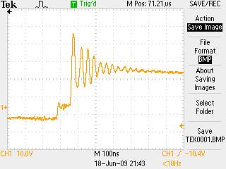
[00:16:29] <Flipp_> why when the leading edge begins to increase
[00:16:38] <Flipp_> does it overshoot and oscillate around V for a bit?
[00:16:56] <Flipp_> https://c2.staticflickr.com/4/3644/3637681038_a8b11255fe.jpg
[00:16:59] <Flipp_> something like that
[00:17:04] <N1njaneer> cap freqs: In a general sense yes. The filter that is formed with a capacitor is always a function of the capacitance plus a resistance somewhere. Generally for basic decoupling you are forming a simple RC low-pass filter that rolls off high frequency noise. And generally the higher the value of the cap, the higher the frequency of interest. 10uf is great for bulk/tank decoupling at the power
[00:17:04] <N1njaneer> supply entrance, but 0.1uf and often 0.01uf placed at the power pins of most devices is usually all you need.
[00:17:35] <N1njaneer> Couple thoughts on that --
[00:18:07] <N1njaneer> What kind of scope probe are you using to tap the clock, and are you using a 10x? Some of that is quite likely induced ringing in the actual scope probe pickup.
[00:18:37] <N1njaneer> Most commonly you'll see higher speed clock edges become more "damped" than the ringing due to intentional slew-rate limiting.
[00:19:15] <Flipp_> hm, okay, I think I got the idea behind caps. I guess I still need to calibrate my own head as to the ranges (10uf vs 1pf)
[00:19:58] <N1njaneer> It's entirely possible you ARE getting ringing, but I'll wager it may be more a function of how you are probing. Make sure you have a hook to ground as close as possible to where you are making the probe reading, and try to use a 10x if you are measuring anything but the lowest of frequencies. Scope probes are generally designed for higher bandwidth only in the 10x setting.
[00:20:13] <Flipp_> so I guess I'm asking more generally; I've seen ringing like that on the EEG/ECoG arrays I used to work with, and their bleed-off tended to be coupled to the DC filtering
[00:21:00] <Flipp_> so it sounds like that's a function of the sampling/filtering of the scope more so than the signal being recorded itself?
[00:21:35] <N1njaneer> 0.01uf = 10,000pf, so 10uf is 10,000,000 (10 million) pf -- so about 7 orders of magnitude between 1uf and 1pf :D
[00:22:28] <N1njaneer> The ringing may certainly be there depending on what you are measuring, but generally the goal is to damp it out ringing/overshoot in most cases, since it leads to a variety of problems including significant problems related to EMC
[00:22:36] <Flipp_> haha, yup. I guess I just gotta wrap my head around when each are used. I mean, given their size I can ballpark that the 10uf electrolytic ones are used for smoothing power, and pf-scale (ceramic?) ones are used for oscillating signals
[00:23:03] <N1njaneer> For general decoupling, 0.1uf is your friend.
[00:24:02] <Flipp_> is there a reason why using a 10uf capacitor would be bad when a 0.1uf capacitor would work?
[00:24:06] <N1njaneer> There was a board we did a while back that had both GPS and WiFi on it, and that required literally an infection of 8pf and 10pf caps all over practically everything to help supress any issues with the 2.4Ghz WiFi and the GPS component. It worked well - passed radiated emissions testing with something like a 12dB margin :)
[00:24:38] <Flipp_> ha, yeah, I can see why the RF might be a problem there :)
[00:24:53] <N1njaneer> Yes, again, the roll-off response is a function of the RC filter formed by the capacitor being the C component -- the smaller the value of C, the higher the frequency will be if R is constant.
[00:25:04] <N1njaneer> As far as your question regarding "no true sine wave"
[00:25:18] <N1njaneer> It's a fairly easy thing to think about
[00:25:32] <N1njaneer> Fourier theory says that only pure sine-waves actually exist in the frequency domain.
[00:25:48] <N1njaneer> When you have a 1Khz sine wave, you have a 1Khz sine wave, and that's it.
[00:26:30] <N1njaneer> If you take a 1Khz sine wave, and you start adding more sine-waves on top of it (at every 3rd harmonic) you will start to get a more and more squared-off square wave
[00:27:35] <Flipp_> yup, got that part. in the limit you can get a "true" square wave, but that's the mathematical limit; electrical systems aren't ideal systems and can't approach them, right?
[00:27:39] <N1njaneer> Here's a quick picture to help --
http://www.bores.com/courses/intro/freq/3_ft.htm
[00:27:54] <Flipp_> err, I mean, can get close, but there's a physical limit
[00:28:06] <Flipp_> yup yup
[00:28:37] <N1njaneer> You CAN, but the problem is the "squarer" the edge, the higher the frequency you need, and thus more energy. So I guess it kind of comes down to a power problem at the end of the day.
[00:28:52] <N1njaneer> But --
[00:29:02] <N1njaneer> The inverse is also true here, and usually where the problem lies
[00:29:34] <N1njaneer> If you switch a transistor on and off very fast, it will basically produce a "square wave" -- on, off, on, off, very fast, if not intentionally slewed (in the most basic sense)
[00:30:00] <N1njaneer> If the transistor has enough energy avaliable, it will create a sharp edge to the square wave that is effectively produced
[00:30:44] <N1njaneer> The problem this creates is that even if the square wave is, say, a 1Mhz square wave, you now have created energy at all of the upper harmonics required to make that square wave a square wave.
[00:31:19] <N1njaneer> If you look at a square wave on a spectrum analyzer, you'll see the fundamental, but then you'll see all of the harmonics as they go up and up and up.
[00:32:07] <Flipp_> so in the case of the 1Mhz, you'd see "ripples" at N*1Mhz?
[00:32:17] <N1njaneer> From an EMC perspective this is very bad, because you are unduely creating radiated emissions, because every time that high-frequency field passes through something that changes the impedence, energy from the electromagnetic field will basically "jump off" and you've just created a transmitter :)
[00:33:55] <jadew> what are you guys talking about?
[00:34:21] <N1njaneer> For square wave it would be the 3rd, 5th, 7th, 9th, etc harmonics up from the fundamental
[00:34:21] <Flipp_> huh. but the "power" (interference? not the word I'm looking for) of that transmission is very dependent on the path the field takes, right?
[00:34:41] <N1njaneer> Flipp_: Yes.
[00:34:59] <N1njaneer> jadew: Hi jadew! Just shooting the shit about random stuff :)
[00:35:12] <jadew> heh
[00:35:32] <N1njaneer> Flipp_: Impedence was until recent a hard concept for me to really grasp because no one had explained it very intuitively
[00:35:54] <N1njaneer> I can understand resistance, and impedence is KIND OF like resistance (and also measured in ohms) but it's not the same thing.
[00:36:24] <Flipp_> hey jadew :) I'm just gettin' schooled :D
[00:36:25] <N1njaneer> The easiest broad-stroke way to think about impedence is "a change to the velocity of the electromagnetic field"
[00:36:48] <N1njaneer> Most people assume electricity just propogates at the speed of light, but it doesn't.
[00:37:40] <N1njaneer> You have to bend your brain to think about the fact that the flow of the current is really a flow of the electromagnetic field energy and NOT actual electrons. Electrons actually typically move really, really slow - inches per second or less.
[00:38:01] <jadew> the way I see impedance is as a bunch of EM elements interracting with the signal, making it slow by chargning and discharging this continous line of EM elements
[00:38:07] <N1njaneer> So when the electromagnetic field propogates along, everything is happy as long as it doesn't change velocity
[00:39:05] <N1njaneer> The field generally propogates as a function of the dielectric constant of whatever it's traveling in - for an FR4 circuit board, the dielectric constant generally puts it at about half the speed of light, but this also assumes a nearby return-path like a ground-plane, etc.
[00:39:18] <N1njaneer> So now going back to the velocity thing
[00:39:35] <Flipp_> it radiates... radially, right? like right-hand-rule kinda?
[00:39:50] <N1njaneer> A lot of times you hear people talking about "impedence matching" with sources and cables and things.
[00:40:09] <jadew> Flipp_, yeah, but it looks different in a transmission line on the PCB
[00:40:14] <Flipp_> e.g. along a trace, so if a trace takes a 90* turn, the velocity of the field changes (the direction)
[00:40:19] <jadew> most of the EM is in the dielectric
[00:40:25] <N1njaneer> If you have an impedence mismatch, you will not efficiently couple the energy
[00:40:25] <jadew> between the strip and the return path
[00:41:35] <N1njaneer> If you have a trace on a PCB, and slot in the plane below it, the field above CANNOT jump over the gap in the trace until the opposing return field on the ground plane goes AROUND the slot below it. This causes an impedence mismatch in the signal, and the propogation gets screwed up, energy is lost, the waveform distorts, and you lose energy. :)
[00:42:05] <N1njaneer> This is why you generally never ever ever EVER route high-speed signal traces over plane-splits or gaps on planes adjacent to the signal :)
[00:42:28] <N1njaneer> Flipp_: Here's another thought to (possibly) blow your mind
[00:42:52] <N1njaneer> The reason you can see your reflection in a window (more easily at night) is fundamentally because of an impedence mismatch!
[00:43:21] <N1njaneer> The air to glass interface causes the propogation of the light to slow when it hits the glass when passing from the air
[00:43:25] <Flipp_> n1njaneer: that's similar to water refraction, right?
[00:43:39] <N1njaneer> Refraction IS impedence mismatch :)
[00:43:49] <Flipp_> yeah, thought so :)
[00:44:12] <N1njaneer> An AR (anti-reflective) coating is effectively nothing more than a clever attempt at impedence matching
[00:44:51] <N1njaneer> Light is as much an electromagnetic wave as a field is propogating on a trace, so the same fundamental behaviours occur. And it's honestly quite weird!
[00:46:15] <jadew> http://dumb.ro/screenshot/8oDuV.png
[00:46:22] <jadew> 10 MHz square wave
[00:47:01] <Flipp_> hm. interesting
[00:47:14] <N1njaneer> Just as "white" light refracts in to a spectrum of color in anything with a high index of refraction since the different wavelengths propogate at slightly different speeds, the same happens to a "square" wave passing through an impedence mismatch -- the harmonic phases essentially become "spread out" which destroys the niceness of the square wave.
[00:48:07] <N1njaneer> Incidentally, this is why you absolutely need a multi-layer circuit board that has ground planes and controlled impedence when you start working with very high speed signals - they simply can't flow intact in any meaningful way over useful distance without it.
[00:48:34] <N1njaneer> Also, jumping back a bit --
[00:48:34] <jadew> http://dumb.ro/screenshot/DBN75.png 10 MHz square wave with 10 ns edges (earlier it had 3 ns edges)
[00:48:38] <Flipp_> huh. and continuous ground planes, right?
[00:49:09] <Flipp_> since you mentioned that a trace going across a gap in the ground plane causes an increase in energy (and a slowdown in the signal)?
[00:49:15] <jadew> N1njaneer, and why FR4 is not great for it
[00:49:40] <jadew> its not homogenous so its dielectric constant is all over the place
[00:49:57] <Flipp_> jadew: why is the 2nd harmonic not as pronounced?
[00:50:17] <jadew> Flipp_, gets canceled
[00:50:22] <N1njaneer> If you are sending serial data over something like RS485, you will generally use a slew-rate-limited driver, because this helps to reduce the higher frequency components in the signal. And the twisted pair helps to maintain a constant impedence down the length of the transmission line while minimizing the cross-section of the EM field, which reduces the common mode noise and likelyness of radiating
[00:50:23] <N1njaneer> or picking up spurious energy.
[00:51:11] <N1njaneer> jadew: Yep, certainly when you get up to the RF side of things there's a lot of stuff far nicer than FR4. But for most digital stuff is usually suffices if you do multi-layer controlled impedence boards. :)
[00:51:34] <N1njaneer> Anyhow, that's a lot more than I wanted to yammer about, but hopefully it's useful.
[00:51:36] <Flipp_> n1njaneer: hm. a bit tangential, but is that the underlying difference between cat5 and cat5e cables, and why the latter can transmit information faster?
[00:51:43] <Flipp_> oh, quite!
[00:51:46] <zerowidth> "controlled impedance", does that mean by design, where the traces/planes go, or by the material the board is made of?
[00:51:46] <N1njaneer> It's fun seeing how stuff fits together. :)
[00:51:57] <zerowidth> N1njaneer: bookmarking all this to read up on later, thanks
[00:51:58] <jadew> I actually have to go to the post office and pick some boards from seeedstudio, I made several microstrips on them, to see which width is best with their 1mm width, 2 layer boards
[00:52:01] <Flipp_> please don't apologize for helpin' me learn :)
[00:52:34] <jadew> zerowidth, all of that
[00:52:51] <N1njaneer> Flipp_: Mostly has to do with controlled impedence. If you look at the standard specs, they specify how many twists-per-unit-length the conductors have to get. The twists and control of manufacturing help to control the impedence over longer distance.
[00:52:54] <jadew> you take into account the dielectric, trace length, width, everything
[00:53:11] <N1njaneer> zerowidth: Yep, what jadew said.
[00:53:21] <zerowidth> cool
[00:53:30] <zerowidth> trace length, is that why i see squiggles sometimes?
[00:53:36] <N1njaneer> zerowidth: If you get to this point, though, generally your board layout software will do most of the heavy lifting at times.
[00:53:55] <N1njaneer> zerowidth: That's generally for skewing the timing so signals all arrive at the same time on a bus.
[00:54:00] <zerowidth> ahh
[00:54:07] <zerowidth> heh, that's when the expensive software kicks in? i only just designed my first pcb with kicad a couple weeks ago
[00:54:16] <N1njaneer> zerowidth: It was very common to see clock snaking on the main clock line on almost all PCI cards :)
[00:55:08] <Flipp_> n1njaneer and jadew: thanks so much for the lessons! gotta run and pick up the fiancee, but got this convo saved for later refreshin' :)
[00:55:15] <N1njaneer> zerowidth: But even with clock-snaking there's actually a minimum seperation distance you need between the switchbacks, else if they are too tightly packed the field will literally just partially flow laterally OVER them rather than following the snaking. Because it really does not want to follow the snaking. :)
[00:55:38] <N1njaneer> Flipp_: No prob! I'm almost always logged in. Poke anytime. Nice chatting with you :)
[00:55:38] <Flipp_> this stuff is complicated... but fun! learnin' more in this channel than I did in college :P :D
[00:55:41] <zerowidth> does frequency have something to do with that too?
[00:55:56] <N1njaneer> Flipp_: Just don't let it overwhelm you!
[00:55:59] <Flipp_> aye, agreed!
[00:56:00] <jadew> zerowidth, yeah
[00:56:10] <jadew> at some frequencies, opens are no longer opens
[00:56:20] <Flipp_> n1njaneer: bah, overwhelm? just means there's more to learn! :D
[00:56:23] <N1njaneer> Flipp_: Learn it as it becomes relevant to what you are working on, but keep the general concepts in the back of your mind to look up when you think they might start to apply.
[00:56:23] <rue_house> and wires no longer conduct
[00:56:29] <jadew> yeah
[00:56:36] <Flipp_> exactly!
[00:56:41] <Flipp_> cheers! take care
[00:56:50] <rue_house> bascially, the rules of electricity as you know them go out the window
[00:58:02] <N1njaneer> Yep, basically when any frequency starts flowing over a length greater than 1/10th the wavelength of the frequency, you generally have to start thinking of the connection as a transmission line instead of a conductor, since the characteristics of the EM field start to play much more heavily than just the thought of conductance.
[00:58:06] <jadew> well, they're still the same but some details take over
[00:58:44] <N1njaneer> It's weird, because intuitively you think of conductors just conducting things, but at lower "human" speeds -- you tap lights to batteries, you tap DC continuity on a multimeter, etc.
[00:59:04] <zerowidth> reading scrolback, thanks for the tip on brownout detection
[00:59:39] <jadew> I got into RF a few months ago and I have to say that I'm more confident now when I'm disigning digital boards
[00:59:45] <N1njaneer> zerowidth: No prob. That one was kind of a real pisser, but again a great example of Atmel helping out to identify the problem. Easy fix, and easy preventative practice for the future :)
[01:00:36] <jadew> I think RF should be studied first and then digital
[01:00:39] <N1njaneer> jadew: RF is still a lot of black magic to me, but I agree with you -- there's a lot of general layout guidelines that apply that just make digital layout "work" correctly if you follow the practices. But RF certainly drives that point home directly. RF is magical!
[01:00:40] <rue_house> I need to implement my brain on a 2560, any ideas?
[01:01:23] <N1njaneer> 2560 is a great part, have used it for a bunch of designs :)
[01:01:42] <N1njaneer> Run it at 5V if you can, so you can get the 16Mhz out of it!
[01:01:48] <rue_house> ok
[01:02:06] <rue_house> can I use avrdude to get an image of my brains firmware?
[01:02:38] <jadew> the code is obfuscated
[01:02:51] <rue_house> damn proprietory !@#%$!#$^!
[01:03:02] <zerowidth> rue_house: careful with high-voltage fuse reprogramming too
[01:03:10] <rue_house> ok.
[01:03:40] <N1njaneer> Use debugwire, ground your hand and touch the wire to your tounge.
[01:04:35] <jadew> I remember several years back IBM was making huge progress with blue brain
[01:04:42] <jadew> I bet they're much further now
[01:05:10] <jadew> chances are someone already has a working brain with some poor guy's firmware in there
[01:06:57] <jadew> actually they probably have a database of brains
[01:07:04] <jadew> must suck
[01:07:20] <jadew> "ok, we're going to reset you now, bye Jack"
[01:07:43] <jadew> "Hi Jeniffer. Don't be afraid."
[01:09:26] <jadew> altho, I guess they don't just shut them down, unless they're testing quick things
[01:09:45] <jadew> otherwise they'd probably save all the sessions
[01:10:50] <jadew> in fact... is anyone here running in an artificial brain?
[01:11:50] <jadew> I guess they wouldn't let them online
[01:55:20] <aczid> oh boy, I should have stayed away from aliexpress... just did a quick count and there are 35 packages coming my way from china D:
[01:58:21] <jadew> aczid, don't worry, they take random ammounts of time to arrive
[01:59:17] <aczid> yeah that's true
[01:59:29] <aczid> but all over the course of the next 2 months I figure
[02:18:15] <Valen> it'll be a suprise every few days
[02:18:59] <Valen> http://xkcd.com/576/
[02:36:47] <malinus> jadew: it will be like christmas all over
[02:37:10] <malinus> packages distributed over a month or so, small presents every day!
[02:41:39] <jadew> that's how I see them too
[02:41:49] <jadew> gifts from china
[02:42:34] <jadew> they're even marked as gifts
[02:42:54] <malinus> Usually, I don't even remember what I've ordered. So it's also the "oh right THAT"
[02:43:20] <jadew> same here with small exceptions
[06:15:08] <malinus> Why would you even use C, when we have bascom for the avr?
[06:18:11] <Lambda_Aurigae> because some of us don't want to pay for bascom
[06:19:53] <malinus> hehe
[06:21:34] <Lambda_Aurigae> but of course, we are all fools for using C when there is a nice interpreted forth for the AVR....and it's much faster than C.
[06:24:43] <megal0maniac> Have we forgotten about assembler?
[06:25:59] <Lambda_Aurigae> but the forth interpreter is written in assembly so it's faster.
[06:26:04] <Lambda_Aurigae> or so we have been told.
[06:26:51] * Lambda_Aurigae goes back to porting picoC to the AVR
[07:28:56] <vsync_> lo folks, haven't been on for a while. Did that mark guy end up inside the rock already?
[07:43:38] <theBear> err, sure, yeah, sounds feasible
[12:44:43] <uskerine> hi, when you use an Arduino UNO, is the hardware UART used for programming or is it free? (example this ->
http://www.ebay.es/itm/BUENO-Arduino-Compatible-UNO-R3-ATmega328P-CH340G-USB-Cable-Modelo-Mejorado-1pc-/171629191080?pt=LH_DefaultDomain_186&hash=item27f5e59fa8)
[12:48:38] <specing> free?
[12:49:11] <uskerine> in Arduino Micro, the only UART of the ATmega328P is used to download the code -via Arduino loader-
[12:49:26] <uskerine> so when attached to the PC to be programmed, it is not free
[12:49:26] <specing> uskerine: arduino uses a bootloader right? (mind you we don't use the arduino environment in this channel)
[12:49:36] <specing> It is not an arduino micro
[12:49:38] <Tekkkz> Hello
[12:49:41] <specing> the chip is an AVR
[12:49:49] <specing> and it is an AVR ATmega328P
[12:49:54] <uskerine> I know that specing
[12:50:12] <specing> Now that we cleared this up
[12:50:55] <specing> At startup, the reset vector points into the code area for the bootloader
[12:51:19] <specing> after the bootloader is done, it will jump into the main application area
[12:51:49] <specing> the keyword being *done*. Because when it is done, it will not use uart any more
[12:52:42] <uskerine> yeah but you can not have attached at the same time something to the UART (say a module controlled by UART) and the PC, right?
[12:52:59] <uskerine> so that's what I mean when I say it is not free
[12:53:13] <uskerine> is already used to download the code
[12:54:05] <specing> why not? It already downloaded the code
[12:57:00] <uskerine> assume that you are all time downloading the code
[12:57:23] <uskerine> like in a debugging/prototyping environment
[12:57:32] <uskerine> so you can not connect at the same time the module and the PC to same UART port
[12:58:33] <LeoNerd> ???
[12:58:46] <LeoNerd> Share it on the PC side. Programmer and serial console/monitor/whatever using the same port
[12:58:50] <Tekkkz> Hi LeoNerd
[12:58:53] <LeoNerd> That's what *everyone* does like.. all the time
[12:59:46] <Tekkkz> LeoNerd: you played today with m32u4 or still nt?
[12:59:51] <LeoNerd> Nope
[12:59:54] <LeoNerd> Unlikely to for a couple of week
[12:59:55] <LeoNerd> s
[13:00:00] <Tekkkz> okay
[13:00:02] <uskerine> LeoNerd so you have TX, RX from ATmega connected to RX and TX from PC and at the same time connected to RX and TX from module?
[13:00:10] <LeoNerd> "from module"?
[13:00:11] <LeoNerd> What module?
[13:00:17] <uskerine> a WiFi module
[13:00:21] <uskerine> which uses serial
[13:00:23] <LeoNerd> Ohright.. some *other* thing
[13:00:27] <uskerine> right
[13:00:30] <LeoNerd> You could do that, yes. It might work.
[13:00:37] <Tekkkz> LeoNerd: you remember i wanted to figure out how to use lufa for usb communication?
[13:00:44] <uskerine> I think it won't work
[13:00:48] <LeoNerd> -technically- you're then stuck doing two drivers of the Tx line
[13:00:53] <LeoNerd> But in practice that seems to work OK
[13:01:02] <uskerine> I don't see how it will work
[13:01:03] <LeoNerd> Tekkkz: YEs. And remember I said there's surely thousands of tihngs already ot help you?
[13:01:25] <uskerine> the module will receive data from the PC and will not be able to see "that's the downloading part of the communication, I will not mess around"
[13:01:27] <LeoNerd> uskerine: A small resistor on each side to limit current flow; UARTs usually idle-high
[13:01:35] <LeoNerd> No it won't
[13:01:46] <LeoNerd> The module will only receive the AVR's *replies* to the PC's requests
[13:01:50] <Tekkkz> nono, it will be easy to just look at the lufa's example, but, LeoNerd, i was too lazy to do this today :D
[13:01:52] <LeoNerd> Which likely will make no sense to it at all
[13:01:56] <LeoNerd> So hopefuully it will ignore
[13:02:02] <LeoNerd> If you find that doesn't work, stick some buffers in there
[13:02:05] <uskerine> I am not worried about the limit current, but about the communication
[13:02:18] <LeoNerd> Use a spare GPIO pin on the AVR chip to control a set of 125/126 chips, or somesuch
[13:02:47] <LeoNerd> Give it a digital switch that normally means the UART <-> FTDI/similar to PC connection is active, but when the AVR starts up it can hit a pin to instead redirect it to UART <-> Wifi module
[13:03:00] <LeoNerd> Tekkkz: well I can't help you overcome your own laziness
[13:03:01] <uskerine> ihm
[13:03:03] <uskerine> uhm
[13:03:07] <uskerine> like using a CHIP ENABLE signal
[13:03:07] <uskerine> ?
[13:03:12] <LeoNerd> Yeah, similar
[13:03:22] <uskerine> that sounds great
[13:03:26] <LeoNerd> Except that you'd then be constructing the hardware to create that CE yourself out of some logic chips
[13:03:35] <Tekkkz> LeoNerd: ofc not, but i will do it on the weekend, if i got it then, you wanna get informend about how easy it is?
[13:03:45] <uskerine> well the module actually has a CE signal
[13:03:46] <uskerine> already
[13:03:47] <LeoNerd> Annoyingly, I don't think you can easily get a chip with both 125 and 126-style gates in it...
[13:03:49] <uskerine> so it is as easy as you suggested
[13:03:50] <LeoNerd> Ah, ewll there you go
[13:03:56] <LeoNerd> Hopefully you don't even need any more hardware
[13:04:10] <uskerine> what is the state of the ATmega ports on reset?
[13:04:21] <uskerine> -whcih corresponds to downloading code I guess-
[13:04:41] <LeoNerd> They're all Hi-Z
[13:04:41] <uskerine> should a pull-up pull-down resistor be enough for the CE?
[13:05:04] <uskerine> to get that stuck to the right DISABLE value until the ATmega is working -and the FTDI chip to the PC is no longer needed-
[13:05:20] <LeoNerd> Soyeah, if you just use a pull{up/down} to hold it in the inactive state during the bootloader, you can then active drive it in the correct state once your program starts
[13:05:38] <uskerine> sounds fine to me, I'll try that
[13:05:52] <uskerine> I was implementing a software UART (already finished the TX part, including buffer)
[13:06:00] <LeoNerd> Ugh.. yeah don't do that
[13:06:12] <uskerine> well I will finish the code, you never know when you will need one
[13:06:25] <uskerine> I finished the TX part and it works superb -including buffer-
[13:06:32] <LeoNerd> Also, whne I'm working on a 328 I tend to use the ISP6 header for programming, that way you don't need to waste the UART on it
[13:06:39] <LeoNerd> It means I have a real UART for real purposes :)
[13:06:52] <uskerine> I purchased an AVR ISP
[13:06:54] <uskerine> cable
[13:06:59] <uskerine> but I don't have any right now
[13:07:00] <LeoNerd> .oO( Or two UARTs if it's a tiny841 ;) )
[13:07:08] <Tekkkz> uskerine:
[13:07:19] <Tekkkz> if you want to use usb to programm an atmega328p
[13:07:29] <Tekkkz> http://matrixstorm.com/avr/tinyusbboard/
[13:07:33] <Tekkkz> have a look at this
[13:07:41] <Tekkkz> the bootloader is also available for 320p
[13:07:46] <Tekkkz> *328p
[13:07:57] <Tekkkz> its not using uart
[13:08:06] <LeoNerd> Eh.. it's basically just a USBASP yes? You can buy those for like, $6
[13:08:11] <Tekkkz> nono
[13:08:17] <Tekkkz> but it programms itself
[13:08:25] <Tekkkz> not just a usbasp
[13:08:31] <Tekkkz> it uses usbasp, but is not one
[13:08:35] <LeoNerd> Ohright. Yeah, I don't really see the point of that :P
[13:08:53] <Tekkkz> its an own board which bootloader is similar to usbasp but it
[13:09:00] <Tekkkz> is an own board
[13:09:02] <LeoNerd> Having a real USBASP or whatever means I waste exactly zero IO pins, zero words of FLASH and zero startup cycles on a bootloader :)
[13:09:06] <Tekkkz> which program itself
[13:09:29] <Tekkkz> ahh no
[13:09:40] <uskerine> but does that use JTAG?
[13:09:48] <Tekkkz> nono
[13:09:50] <Tekkkz> just usb
[13:11:46] <uskerine> I am not following
[13:11:49] <uskerine> you
[13:12:16] <Tekkkz> hä?
[13:13:28] <uskerine> so what uses that usbasp to programm the ATmega328P? which pins?
[13:13:50] <Tekkkz> look at the datasheet form the board i sent you
[13:13:53] <Tekkkz> wait
[13:14:15] <Tekkkz> you should checkout rev3
[13:14:20] <Tekkkz> you can build it alone
[13:14:25] <Tekkkz> without an kit or extra parts
[13:14:38] <Tekkkz> its just using pd6 and pd7
[13:14:46] <Tekkkz> but you can change this
[13:14:49] <Tekkkz> and use every you want
[13:15:21] <uskerine> it uses SPI
[13:15:27] <Tekkkz> nono
[13:15:32] <Tekkkz> you programm it via usb
[13:15:34] <Tekkkz> no isp
[13:16:20] <uskerine> it is amazing uses USB, as the ATmega328P has NO usb peripheral
[13:16:41] <Tekkkz> yeah
[13:16:45] <Tekkkz> it uses the vusb lib
[13:16:53] <Tekkkz> http://www.obdev.at/products/vusb/index.html
[13:17:00] <Tekkkz> and with that the usbasp
[13:17:06] <Tekkkz> and with that the bootloader is made
[13:17:09] <Tekkkz> to program itself
[13:17:13] <Tekkkz> not to be a programmer
[13:17:26] <Tekkkz> but ofc you can write easily a firmware to be a programmer, too
[13:18:03] <uskerine> i think I will try the solution LeoNerd suggested, it is the easiest and I have all the HW already here in the workbench
[13:18:14] <Tekkkz> wait
[13:18:17] <Tekkkz> you dont understand me
[13:18:20] <Tekkkz> so
[13:18:23] <Tekkkz> what do you have?
[13:18:40] <Tekkkz> usb-connector m328p diodes resistors etc?
[13:18:43] <uskerine> I have an Arduino Micro Pro and one of those usb to serial (FTDI) pcbs
[13:18:52] <Tekkkz> ehh
[13:18:57] <LeoNerd> Oh, then you don't have a USBASP?
[13:18:58] <Tekkkz> why dont you use aruino bootloader
[13:18:59] <uskerine> I use arduino micro bootloader with Atmel Studio
[13:19:18] <uskerine> No I don't have a USBASP
[13:19:26] <Tekkkz> i thoguth you have a "blank" lonely m328p chip
[13:19:27] <LeoNerd> Ah; then no use of the ISP6 header for you
[13:19:30] <Tekkkz> you dont need usbasp
[13:19:32] <uskerine> I am amazed on the complexity of programming those chips
[13:19:43] <LeoNerd> s/complexity/flexbility/
[13:19:47] <Tekkkz> you dont have a lonely m328p chip!??
[13:19:49] <uskerine> LeoNerd I was actually wondering what is the ISP6 header?
[13:20:02] <LeoNerd> The 2x3 pin header that's usually labeled "ISP"
[13:20:06] <LeoNerd> For actually programming the thing :P
[13:20:11] <uskerine> I also ordered a board with 168P (which uses JTAG) and a USB to JTAG board
[13:20:29] <uskerine> LeoNerd but what pins does that uses? SPI ones?
[13:20:37] <LeoNerd> Eh.. ~nobody uses JTAG to program AVR chips
[13:20:38] <Tekkkz> mhhh, why no blank chips and put them together by your own like tinyusbboard rev3?
[13:20:52] <uskerine> :)
[13:20:55] <uskerine> ok good to know
[13:20:59] <LeoNerd> ISP6 uses the ISP pins.. *usually* but not always, those correspond to the hardware SPI pins
[13:21:01] <uskerine> I think I will buy a USBASP to use ISP
[13:21:07] <uskerine> LeoNerd good! finally I understood
[13:21:09] <uskerine> :)
[13:21:12] <LeoNerd> Occasionally they're not; e.g. any of the tiny chips that don't even have an SPI module...
[13:21:24] <Tekkkz> you dont need to buy a usbasp
[13:21:26] <LeoNerd> But ISP is basically an SPI-driven protocol
[13:21:29] <Tekkkz> just buy a tinyusbboard kit
[13:21:44] <Tekkkz> there are still some pre-packet kits left with the m328p
[13:21:45] <uskerine> LeoNerd, anyway I am happy to use the FTDI and the Arduino Micro, it is really unexpensive, my only problem was that it was actually blocking the hardware UART of the 328P
[13:21:49] <Tekkkz> its a special edition of it
[13:21:58] <Tekkkz> its black withh gold
[13:22:04] <Tekkkz> nice edition,verry rare
[13:22:05] <LeoNerd> uskerine: Wellyes, that comes baack to the core of the problem. That way means you need the UART for programming
[13:22:08] <uskerine> Tekkkz an Arduino Micro costs 2Euros shipment included
[13:22:11] <uskerine> I bought like 20 or so
[13:22:21] <LeoNerd> uskerine: Whereas, if you used ISP then you wouldn't *need* to use the UART for programming, and thus that whole problem goes away
[13:22:25] <Tekkkz> and its shit compared to the tinyusbboaard!
[13:22:31] <specing> uskerine: AVR!
[13:24:21] <uskerine> what is wrong with the arduino micro? it is just a 328P conveniently cheap and easy to find
[13:24:38] <LeoNerd> Yah; the micro is pretty nice
[13:24:49] <uskerine> I mean, 2 Euros, shipment included
[13:24:51] <Tekkkz> Its an arduino
[13:24:52] <uskerine> :-!
[13:24:54] <LeoNerd> If you just want a 328 on a breakout board, it's easy and cheap to get hold of :)
[13:24:54] <Tekkkz> i hate arduino
[13:25:07] <LeoNerd> The "only" problem with it is the pin numbering :(
[13:25:17] <LeoNerd> But that's not too hard to solve with a little piece of paper reference chart
[13:25:18] <Tekkkz> pin numbering??
[13:25:21] <uskerine> well I printed one of those PDFs which includes arduino numbers and AVR ports
[13:25:41] <LeoNerd> Yes. All the Arduino boards silkscreen on the Arduino pin numbering, which isn't the actual Atmel hardware naming of those pins
[13:25:49] <LeoNerd> Arduino == 0, 1, 2, 3, ....
[13:25:59] <LeoNerd> Atmel == PB0, PB1, PB2, ... PC0, PC1, PC2, ....
[13:26:32] <uskerine> sorry, I was saying micro, but it is the promini
[13:26:33] <uskerine> http://www.hobbycomponents.com/images/forum/ProMini_Pinout.png
[13:26:35] <LeoNerd> So the trouble with using an Arduino board and then not running Arduino code on it, is that you have to somehow work out what those pins are in reality. Easy enough with a little paper chart, etc...
[13:26:42] <uskerine> with this PDF that's not an issue LeoNerd
[13:26:46] <uskerine> this image sorry
[13:26:57] <LeoNerd> Yah - that serves as a useful cross-reference
[13:27:10] <LeoNerd> It's only annoying because it's not physically marked on the actual board itself, so you have to look it up
[13:27:25] <LeoNerd> It's a bit of an annoyance but it's not the end of the world
[13:27:42] <LeoNerd> For being able to buy a dirt-cheap 328P breakout board, it's a reasonable cost to pay :)
[13:28:14] <uskerine> exactly
[13:29:09] <uskerine> I will finish the software UART anyway, just for finishing it, it is almost done and it is good practice in AVR (I am new with the architecture)
[13:29:19] <LeoNerd> Eh.. there's plenty of them around online you know
[13:29:38] <uskerine> I found some, but you have to learn how to integrate them
[13:29:48] <uskerine> and I am not sure to have found a full duplex with buffer
[13:30:08] <uskerine> and I need practice anyway so I decided to code it
[13:31:14] <less> Hi guys Im trying to set fuse bits on my atmega 328p
[13:31:18] <less> but without success
[13:31:41] <less> I want to use external crystal and 22pf capacitors
[13:32:15] <less> Im using this calc
http://www.engbedded.com/fusecalc/
[13:33:25] <less> so using this calc I generated folllowing fuses -U lfuse:w:0x7f:m -U hfuse:w:0xd9:m -U efuse:w:0xff:m
[13:33:48] <less> I dont understand why ckdiv8 is selected
[13:34:53] <LeoNerd> It just defaults to being on
[13:35:03] <LeoNerd> You can turn it off if you want.. it does'nt affect the clock generation hardware
[13:36:49] <less> LeoNerd: I tried with 2 atmega and all are unable to program
[13:37:08] <less> So actually Im lost
[13:37:18] <less> how to set this fuses to not block my uC
[13:37:52] <LeoNerd> Well, how are you writing them?
[13:38:09] <less> with avrdude
[13:38:18] <LeoNerd> And what hardware?
[13:38:24] <less> 32mp
[13:38:27] <less> 328p
[13:38:33] <LeoNerd> What programming hardware?
[13:38:37] <less> usbasp
[13:38:53] <LeoNerd> Ok.. and what leads you to believe it isn't working?
[13:39:14] <less> avrdude: error: programm enable: target doesn't answer. 1
[13:39:20] <less> avrdude: initialization failed, rc=-1
[13:39:25] <less> after setting fuse bits
[13:39:39] <LeoNerd> Right; well what clock hardware do you actually have connected to the AVR chip?
[13:39:53] <less> I have crystal 16mhz
[13:39:56] <LeoNerd> If you change the clock to using an external crystal and there isn't a crystal attached, then of course it's going to stop taling to you :)
[13:40:20] <less> Yep I know, but I attached crystal with two capactiors
[13:40:22] <less> 22pF
[13:40:37] <LeoNerd> Infact, I'm not too sure how the chips behave if you change their clock source over SPI
[13:40:41] <LeoNerd> I only ever do that over HVSP ;)
[13:41:00] <less> when I did this I have ckldiv8 selected
[13:41:04] <less> its because of that
[13:41:04] <less> ?
[13:41:13] <LeoNerd> CLKDIV8 is unrelated
[13:41:15] <less> or it should just work with 2mhz
[13:41:19] <less> ok
[13:42:02] <less> what have worked i changed ckdiv8 and uC start working with 8mhz
[13:42:22] <less> I cant make him to work with 16mhz
[13:46:19] <less> LeoNerd: Could you tell me how should fuse bits looks
[13:46:20] <less> ?
[13:46:44] <LeoNerd> Not offhand
[13:46:56] <LeoNerd> The way I'd know that is by using one of those online fuse calculators; you seem to already have one
[13:47:06] <LeoNerd> So I'm unlikely to find a better answer than you already have
[13:47:54] <less> avrdude: initialization failed, rc=-1 it means end of life for my uC's ?
[13:48:45] <LeoNerd> It means that avrdude can't talk to the chip currently
[13:49:02] <less> yep, but is there a way to make hm to talk :)
[13:49:18] <N1njaneer> less: Try lowering the speed very slow on the programmer via avrdude if it's not communicating.
[13:50:40] <less> N1njaneer: Bitclock in avrdude ? to what number ?
[13:51:55] <LeoNerd> If it's a USBASP there may also be a "slow clock" jumper on the board
[13:52:25] <less> there is only voltage jumper
[13:52:28] <less> 3,3 and 5
[13:52:50] <LeoNerd> Ah. That's a shame. Mine has two
[13:52:58] <LeoNerd> (well, three including the SELFPRG one but that's unimportant today)
[13:53:07] <N1njaneer> less: 125Khz or less
[13:53:58] <N1njaneer> less: ISP communications always need to be done at a rate that is LESS than 1/4 the clock speed the device is running at. From the factory they generally default to internal 1Mhz RC oscillator
[13:53:59] <less> fuck is working
[13:54:09] <less> I set to 0.5
[13:54:31] <N1njaneer> good!
[13:54:50] <less> Sorry
[13:54:57] <LeoNerd> Awww.. now I've lost a chance to try to sell one of my HVSP boards :P
[13:55:27] <less> give me a second guys :)
[13:55:46] <LeoNerd> Hah! RikusW - literally 10 seconds before you joined, I was talking about my HVSP boards.
[13:55:49] <LeoNerd> you must have good hearing
[13:55:57] <RikusW> Hi LeoNerd
[13:56:04] <RikusW> heh
[13:56:36] <LeoNerd> So.. I measured the capacitance on the crystal lines, by the way. Did I mention that? One of them is 23pF, the other 29pF. or something like that. I forget quite the numbers. But definitely different
[13:56:56] <LeoNerd> I think at this point I might go "Meh" and be annoyed, and redo the board with a smaller crystal
[13:57:13] <LeoNerd> Which sucks piggie because I want to recover all the componetns off the board.. only I lack a hotair station
[13:57:25] <RikusW> did you measure the pwm out frequency ?
[13:57:32] <LeoNerd> I could *buy* myself a hotair, but then that's much more expensive then just getting a new set of parts.
[13:57:37] <LeoNerd> FML
[13:57:45] <LeoNerd> Oh.. hrm. No I haven't tried that yet. I probably should
[13:58:04] <RikusW> If you are careful a heatgun will do
[13:58:19] <LeoNerd> I lack such a thing. All I have is.. well, actually two soldering irons.
[13:58:23] <RikusW> I have one with 2 speed settings and temp control
[13:58:42] <RikusW> A heatgun is cheap compared to a hotair station
[13:59:00] <LeoNerd> Thing is, my board verynearly does work.. it's just a littlebit off... I may be able to tweak the timing somehow to be good enough for my purposes
[13:59:01] <RikusW> preferably get one with temp control
[13:59:24] <LeoNerd> I measure it talking serial at 117kBaud; as compared a target of 115
[13:59:25] <N1njaneer> LeoNerd: An inexpensive heat-gun works fine if you are very careful with it.
[13:59:27] <LeoNerd> 115.2
[13:59:28] <RikusW> I'd still check the pwm frequency just to be sure it is in fact the board
[13:59:36] <RikusW> or the crystal maybe...
[13:59:45] <LeoNerd> N1njaneer: have you seen how dense my board is? :P
[13:59:52] <N1njaneer> Picture?
[13:59:53] <LeoNerd> I can't "be careful with it" in there
[14:00:14] <RikusW> If you get one without temp control use distance from board to control temp
[14:00:16] <LeoNerd> https://twitter.com/cpan_pevans/status/565674460020482049
[14:00:18] <N1njaneer> Heat the entire general area and then use tweezers.
[14:00:40] <N1njaneer> I thought you said it was dense!
[14:00:42] <less> Now i have that avrdude: safemode: hfuse changed! Was d9, and is now ff
[14:00:47] <RikusW> and do heat it slowly at first to warm up the entire board
[14:00:51] <LeoNerd> That photo might also show you why I suck at crystal layout - the bottom pin on the crystal is waaaaay lower down than the top pin, so the trace is a lot longer
[14:00:52] <less> Im typing yes and waiting foerever ;)
[14:00:53] <N1njaneer> There's enough real-estate in there to squeeze in another copy of that board :D
[14:00:56] <LeoNerd> I broke the symmetry
[14:01:16] <LeoNerd> Yeah - when I make a v0.2 board I'll put the MCU and maybe the 595 on the back
[14:01:22] <LeoNerd> Thus leaving more space for the LEDs and buttons on the front
[14:01:31] <N1njaneer> LeoNerd: Symmerty -- that won't matter at all for something this small.
[14:01:48] <LeoNerd> Also it was a terrrrrible idea of mine to have an open analog line with 1Mohm pulldown for the buttons.. it's noisy. I can induce noise by touching the board
[14:01:54] <RikusW> LeoNerd: I'd try putting on a different crystal too
[14:01:58] <LeoNerd> I don't have any others
[14:01:59] <uskerine> LeoNerd so I bought the USBASP -just in case, it might be useful for the future-
[14:01:59] <N1njaneer> Where are your 0.1uf's for decoupling?
[14:02:02] <LeoNerd> Well, I have two more the same
[14:02:06] <RikusW> to make sure its not the crystal
[14:02:16] <LeoNerd> N1njaneer: see that brown one up the top by the 6pin header
[14:02:48] <LeoNerd> I could try another xtal I guess; I do have three of them
[14:02:48] <RikusW> LeoNerd: change to internal pullup in the avr and make the buttons pulldown
[14:02:59] <N1njaneer> You only have one decoupling cap on the whole board?
[14:03:14] <LeoNerd> RikusW: I've only got one GPIO spare for *all* of the buttons. I'm using an ADC pin to read an analog divider chain
[14:03:22] <LeoNerd> Half of the resistors by the buttons are that chain
[14:03:26] <RikusW> it could be lack of decoupling caps.....
[14:03:31] <_abc_> Hi. How would you guys check serial comms parity between a device and a pc connected with a usb to serial converter?
[14:04:02] <LeoNerd> N1njaneer: There's only two chips on the board - the tiny841 and the 595 to drive the LEDs... and I'm not driving the LEDs at all, not even talking to the chip
[14:04:08] <LeoNerd> And still the clock is off
[14:04:14] <N1njaneer> LeoNerd: You should have a minimum of a 0.1uf per power pin per active device on the board, and then at least one at the power input, as well as generally a larger tank cap like a 10uf near power input.
[14:04:39] <LeoNerd> Mmm.. I can probably solder a couple more over the top for now to test it with then...
[14:04:49] <N1njaneer> Better to have too many than not enough.
[14:04:50] <LeoNerd> But honestly I feel the asymmetry of the crystal lines is the reason
[14:04:57] <RikusW> _abc_: explain a bit more
[14:04:58] <N1njaneer> Not on something this small.
[14:05:04] <LeoNerd> I'll try getting some smaller caps and replace the longer one
[14:05:06] <less> Ok it is working but when put off the capacitors near the crystal
[14:05:24] <LeoNerd> less: did you take account of board capacitance?
[14:05:32] <N1njaneer> LeoNerd: Believe me I've done many dozens of layouts like this. At 8-16Mhz for the AVR stuff it makes no difference.
[14:05:35] <LeoNerd> E.g. if this is on breadboard or stripboard, that can be significant
[14:05:46] <less> LeoNerd: Noo
[14:05:48] <RikusW> _abc_: do you mean check parity in soft uart on the device ?
[14:06:01] <less> in the datasheet were circuit with crystal and two capacitors
[14:06:05] <less> so I used it
[14:06:43] <LeoNerd> N1njaneer: Nono, I mean... The longer xtal wire has much more stray capacitance from the board - the manufacturer suggests 18pF load on the crystal, and I measure a bare board /itself/ as having 29pF before I even put any components on it
[14:07:17] <LeoNerd> (As in: I put my LCR meter probe directly onto a new bare copper board, and got 29pF off just the copper, once I take account of the probes themselves)
[14:07:22] <LeoNerd> That's a huuuuge amount of stray cap from the board
[14:07:49] <N1njaneer> I think it's a bigger problem elsewhere - this shouldn't be nearly this sensitive to those kind of parameters.
[14:07:50] <uskerine> is INT0 and INT1 are fixed in AVR architecture? you must use those pins if want to detect falling edge?
[14:07:53] <LeoNerd> Hrmmm
[14:08:05] <LeoNerd> uskerine: Yup :/ Very few remappable IO pins on AVRs
[14:08:06] <uskerine> *are INT0 and INT1 fixed in AVR architecture?
[14:08:12] <uskerine> ok
[14:08:15] <RikusW> uskerine: year
[14:08:17] <RikusW> yes
[14:08:26] <Tom_shop> yup
[14:08:28] <N1njaneer> When we use quartz with AVR's it's a 22pf per leg and we've never had issues on thousands of boards. Double-check your clock fuse settings perhaps?
[14:08:28] <LeoNerd> (This is one of my continued disappointments :( I want a crossbar switch damnit!)
[14:08:38] <mnms_> Guys if I can ask do you know some free IR library in C ?
[14:08:57] <LeoNerd> N1njaneer: Well, I could try reading the clock fuses, but surely if it was set to anything else, it would just plain Not Work At All?
[14:09:03] <uskerine> yeah, I am used to C8051 where you can do that stuff
[14:09:11] <RikusW> LeoNerd: try adding the 10uF to Vcc and see what happens
[14:09:12] <N1njaneer> mnms_: Many types of "IR" protocol out there -- but there are several, yes. Or trivial to write one.
[14:09:12] <LeoNerd> As it is, it's "working" but with about a 2% timing error
[14:09:15] <LeoNerd> Yeah.. I can try that
[14:09:19] <RikusW> maybe a 100nF too
[14:09:22] <LeoNerd> I can easily solder more caps on the board
[14:09:44] <mnms_> N1njaneer: I would like to get something which is working and ready if possible
[14:09:45] <LeoNerd> annoyingly, I'm never at home with the board when youlot are around to talk to about it :) So I'll have to try it later tonight and report back
[14:09:47] <N1njaneer> LeoNerd: No, if the clock fuses are set wrong you can definately get it to run, but not run correctly.
[14:10:14] <N1njaneer> mnms_: Figure out what IR protocol you need to talk first, then search around :)
[14:10:20] <LeoNerd> N1njaneer: OK.. if it was rnuning off its internal 8MHz osc., say, instead of this external 14.7MHz crystal, then it would be much more than 2% off
[14:10:43] <LeoNerd> Butyes, as it's easy I can check the fuses
[14:11:00] <RikusW> LeoNerd: I've tuned osccal to make it accurate once :)
[14:11:09] <LeoNerd> Thinking about it, it was only powered by the +5V line coming down a USB-UART cable, so that also might help
[14:11:10] <N1njaneer> LeoNerd: Yes, but there are different settings for the clock based on the frequency of the quartz. Usually the dividing line is above or below 8Mhz.
[14:11:11] <LeoNerd> Oooooh OSCAL
[14:11:21] <LeoNerd> Ah
[14:11:33] <RikusW> osccal is only for RC osc
[14:11:35] <LeoNerd> Ah
[14:11:50] <N1njaneer> LeoNerd: Give it clean +5V pwoer and add more decoupling and see if you measure a difference. If the power is crap, it's all down-hil..
[14:11:53] <N1njaneer> +hill
[14:11:59] * LeoNerd nod
[14:12:07] <LeoNerd> OK, well that's two more useful things I can try anyway
[14:12:14] <LeoNerd> Hrmm.. hey I have a crazy idea
[14:12:22] <N1njaneer> I'll be here later tonight if you want to chat more. Have to get a quote out then go load in lasers for a show tonight, then I'll be back :)
[14:12:28] <RikusW> LeoNerd: do you remember the LFUSE setting ?
[14:12:38] <LeoNerd> I don't have to hand any ~10pF caps to try swapping it... but maybe I can solder on a really long piece of 2core speaker wire
[14:12:46] <LeoNerd> and tune that until I get a total load capacitance of 18pF :)
[14:13:01] <N1njaneer> And then compensate the inductance and resistance parts!
[14:13:05] <LeoNerd> Mm.. Or glue two bits of foil to a piece of paper
[14:13:40] <RikusW> was it t85 iirc ?
[14:13:43] <LeoNerd> lfuse:w:0xEE:m
[14:13:45] <LeoNerd> tiny841
[14:14:05] <LeoNerd> # SUT_C=External crystal >8MHz, CKDIV8 off is my comment on that line
[14:14:23] <LeoNerd> Ohyeah
[14:14:29] <LeoNerd> None of the decent online fusecalcs know of the tiny841 :(
[14:14:32] <LeoNerd> Suuuuuck!
[14:14:56] <N1njaneer> LeoNerd: All the more reason to just use Atmel Studio, since all of that is just checkboxes and pulldowns with zero ambiguity
[14:15:08] <LeoNerd> YEah but that's like, huge, and Windows, ...
[14:15:17] <RikusW> generally I've found 0xFF to be safe for use with 14-16 MHz on mega32u2
[14:15:17] <LeoNerd> And also I really like writing code in vim.
[14:15:28] * RikusW likes vim too
[14:15:39] <uskerine> PIN CHANGE INTERRUPTS
[14:15:47] <uskerine> what is that?
[14:16:19] <RikusW> uskerine: it will interrupt when pin state change and only certain pins can be enabled for it
[14:16:38] <RikusW> like any combination on an 8 pin port
[14:16:45] <LeoNerd> OK, LFUSE=0xEE I interpret to mean: crystal >8MHz, startup = 1k clock, CKDIV8 off.
[14:17:05] <LeoNerd> FF looks to be reserved
[14:17:24] <uskerine> so instead of using a given pin for INT0 I could use PCINTn
[14:17:24] <N1njaneer> Not sure why people justify NOT using one of the best dev toolchains out there (and free!) that makes life easy and easily eliminates 50% of the problems that we see come through here just out of the gate. But that's only my preference. People love making things overly complex I have noticed. :)
[14:17:25] <uskerine> right?
[14:18:00] <RikusW> yes
[14:18:01] <LeoNerd> N1njaneer: when I can type apt-get install atmel-studio then I will consider it
[14:18:10] <uskerine> thanks RikusW
[14:18:15] <RikusW> there are some implications if you use sleep mode though
[14:18:23] <uskerine> which implications?
[14:18:26] <LeoNerd> When I can configure it to embed (g)vim as the code editor
[14:18:38] <RikusW> read the datasheet carefully if you do use sleep
[14:19:03] <uskerine> PCINTn seems a bit cumbersome, I think I will go first with INTn
[14:19:09] <_abc_> 20:47 < _abc_> I have a msp2200 based usb to serial converter which works fine with itself on any parity setting. I have atmegas which work fine with the adapter n no parity, and only pass some characters with E or O partity. This has me stumped.
[14:19:10] <N1njaneer> LeoNerd: Atmel Studio is free and far more functional and nice to use than $5K worth of IAR Workbench, and it does all of this for you. Every time you program a part it works. The time savings alone are justifiable :)
[14:19:11] <LeoNerd> PCINTs can only do change notifications; so you get either edge (combined), rather than just one edge, or level-based
[14:19:13] <_abc_> 20:47 < _abc_> I have a msp2200 based usb to serial converter which works fine with itself on any parity setting. I have atmegas which work fine with the adapter n no parity, and only pass some characters with E or O partity. This has me stumped.
[14:19:22] <_abc_> 20:48 < _abc_> Also the avr ALWAYS sends right to host, with selected parity, N O or E. Reception from host is fubar'd on anything but N. Host receives itself fine on any of N O E
[14:19:24] <LeoNerd> N1njaneer: Does it run on Linux?
[14:19:25] <_abc_> RikusW:
[14:19:43] <_abc_> *mcp2200 base
[14:19:44] <_abc_> d
[14:19:47] <N1njaneer> LeoNerd: No, it's Windows only since it's built on top of Visual Studio.
[14:19:53] <LeoNerd> Right. Then it's of no use to me
[14:20:11] <N1njaneer> If you have time to do it the long way round, more power to you. :)
[14:20:16] <RikusW> _abc_: sounds like a weird problem...
[14:20:25] <_abc_> RikusW: Tell me about it.
[14:20:29] <RikusW> why no use it without parity ?
[14:20:40] <RikusW> and checksum the packets instead
[14:20:50] <LeoNerd> Yah; nobody does parity checking these days
[14:20:50] <_abc_> I was trying to use every bit of available error detection since I already checksum data.
[14:20:54] <LeoNerd> Higher-level systems are nicer
[14:21:04] <N1njaneer> And arguably far more reliable.
[14:21:24] <LeoNerd> Parity checking can detect 1-in-2 errors. CRC8s can detect 255-in-256
[14:21:27] <N1njaneer> Parity-check is really only useful for single-bit error checking.
[14:21:35] <_abc_> LeoNerd: Don't say that. Ever worked with cisco and other console serial cables?
[14:21:48] <_abc_> ANY error checking is better than none
[14:22:01] <RikusW> LeoNerd: it seems on most avrs lfuse are similar and it seems 0xEE is for a resonator no crystal...
[14:22:05] <RikusW> *not
[14:22:08] <_abc_> For 99% us-ascii commands I'd be fine with 7E1
[14:22:18] <LeoNerd> RikusW: I'm reading the 841 datasheet here
[14:22:20] <_abc_> Calculating software parity
[14:23:00] <RikusW> LeoNerd: if 0xFF for lfuse seems sane after looking at the t841 ds, use it, it should work
[14:23:01] <_abc_> Or 7O1. I always forget which
[14:23:44] <LeoNerd> RikusW: Uhm what page are you on? ;) I'm on page 30 (section 6.5) where it quite clearly says that CKSEL=1111 SUT=1 is "reserved"
[14:24:20] <RikusW> LeoNerd: just using general avr knowledge that lfuse on most are similar...
[14:24:35] <RikusW> SUT = 01 ?
[14:24:38] <LeoNerd> Yah... but the tiny841 seems to have more different internals than most of the others
[14:24:44] <LeoNerd> It only has 1 SUT bit
[14:24:44] <RikusW> iirc SUT is 2 bits
[14:24:53] <RikusW> ah
[14:25:51] <LeoNerd> Honestly, I'm happy to triplecheck *again* but I'm reasonably sure the fuses are right because if they were wrong it wouldn't work *at all*
[14:26:05] <LeoNerd> I can't see any other fuse setting that would work-but-just-be-wrong-timing like it does
[14:28:15] <RikusW> t841 ds is 18MB it bit largish for GPRS dl ...
[14:29:27] <LeoNerd> Hrm?
[14:30:20] <RikusW> I only have a GPRS connection, 115kbits
[14:30:26] <RikusW> for internet...
[14:30:44] <LeoNerd> Oh.. "ds" == datasheet
[14:30:59] <RikusW> If I get a better modem I might get EDGE which is only double that... :/
[14:31:05] <LeoNerd> mmm
[14:31:20] <RikusW> I could get 3G access, but not here...
[14:31:36] <RikusW> 25km from the nearest town...
[14:32:33] <RikusW> One thing I certainly don't miss is traffic :-D
[14:32:42] <RikusW> only dirt roads around here
[14:33:01] <RikusW> at the moment muddy wet too...
[15:28:32] <uskerine> I know the question is quite open, but does anyone have any insight on how much time does it take to execute a simple line of C code such as an if against a char variable?
[15:28:51] <uskerine> 8MHz clock
[15:30:44] <LeoNerd> To answer that I'd (and I often do) read the disassembly
[15:31:15] <LeoNerd> Then you can see the actual instructions it compiles to. Likely one or two there... a load and a conditional jump. You can then look up the exact number of cycles that takes on your chip's datasheet
[15:31:54] <uskerine> does the number of cycles depend on the instructions?
[15:35:19] <uskerine> how can I see the assembly for a function in c?
[15:53:46] <mark4> lpm/elpm expect a byte address right?
[15:54:22] <mark4> yea nvm ty :)
[16:51:06] <_abc_> Speaking of disasm, there was an app made by someone to completely re-gerenate gcc equivalent source code from a hex file for avr-gcc. The guy was a Russian student. The app vanished. Does anyone know something about that?
[16:51:31] <_abc_> Equivalent code means of course obfuscated-by-optimzer C source.
[16:52:39] <_abc_> http://phys.org/news/2015-03-climate-extreme-winters.html oh noes. It only generates extreme Summers? Yay, look, a DIODE!
[17:03:52] <Horuzar> Hey guys, simple question as I am a noob. Isn't PORTD | = (0 << 6) the same as PORTD &=~ ( 1 << 6)
[17:29:48] <LeoNerd> No
[17:29:57] <LeoNerd> Specifically, |= (something that is zero) doesn't have any effect
[17:30:15] <LeoNerd> |= can only ever turn bits on; but it has no bits to turn on in that case
[17:30:20] <LeoNerd> &= can only ever turn bits off
[18:01:44] <malinus> Horuzar: you could read this
http://www.atmel.com/images/avr_3_04.pdf
[23:10:40] <retrosenator> could someone tell me if avr is obsolete yet?
[23:11:52] <Casper> if avr is obsolete, then pic16 is what?
[23:12:00] <aandrew> heh
[23:12:11] <aandrew> retrosenator: I think your answer is a resounding "no"
[23:12:24] <retrosenator> i was using atmegas like 8 years ago
[23:12:29] <retrosenator> I don't see how they can still be viable
[23:12:43] <aandrew> I use AVRs in new designs
[23:12:46] <retrosenator> compared to arm processors which are cheaper faster etc...
[23:12:54] <retrosenator> are you using xmega or?
[23:13:01] <aandrew> granted, I will put ARMs in more, but for little things AVRs still get my vote
[23:13:07] <Casper> retrosenator: are you sure about arm being cheaper?
[23:13:23] <retrosenator> maybe the attiny is still cheaper
[23:13:37] <Casper> for the same hardware functionality?
[23:13:45] <Casper> dosen't arm require external flash and ram?
[23:13:52] <retrosenator> it would be great if they rebuilt some attiny using 22nm process
[23:13:54] <retrosenator> not all arm does
[23:14:29] <retrosenator> I envision basically making the hardware function identically, but at a higher clock rate possible and much less power
[23:14:35] <retrosenator> I don't see why they didn't do that
[23:15:24] <Casper> cost most likelly
[23:15:46] <Casper> or because they want to do that to their arm series?
[23:17:29] <retrosenator> in that case, maybe some of the attiny are still viable, but the atmega are basically inferior to something like stm32
[23:21:26] <retrosenator> anyway it would be really cool to have 6 pin attiny running at 60mhz using 2 milliamps
[23:21:28] <retrosenator> which is probably possible to achieve
[23:22:12] <Casper> it would also be cool if they hasn't fucked up the uart in attiny85...
[23:22:35] <Casper> I mean, it can do every type of uart, EXCEPT async serial
[23:25:35] <retrosenator> heh
[23:25:43] <retrosenator> can't you do it in software?
[23:26:43] <Casper> yes of course, but it's annoying that they put the hardware stuff there, but screwed it up...
[23:27:56] <Casper> currently, my main issue is that I need to find a way to send data from one master to several slave, that all can be on a different speed (no crystal), using only a single data wire...
[23:28:27] <retrosenator> autocalibrate
[23:28:37] <retrosenator> the slaves automatically calibrate
[23:28:58] <retrosenator> then they adjust their frequency by setting the register
[23:29:16] <Casper> no hardware uart, can't do that
[23:29:16] <retrosenator> i did it when bitbanging usb without crystal
[23:29:27] <Casper> beside, no timer left too
[23:30:28] <Casper> my current idea sound bad... modified 1 wire... i.e. different pulse width for 0 and 1
[23:30:56] <retrosenator> maybe if the data rate is low you have other options
[23:31:17] <Casper> 20kbps
[23:31:43] <retrosenator> maybe you should get an arm heh
[23:32:03] <retrosenator> at least a different avr
[23:33:22] <Casper> it's perfect for the job! or almost :D
[23:34:35] <Casper> I'll probably just do a busy loop counting the itteration of low... less than x = 1, less than y = 0, more than x = reset
[23:34:37] <Casper> hmmm
[23:36:30] <Casper> that could even mean variable bitrate too...
[23:36:44] <Casper> if I transmit inverted, it would transmit faster...
[23:37:43] <Casper> but too much trouble to invert :D
[23:38:03] <retrosenator> you are about 20 years late for such ideas, just get an arm processor and use wifi
[23:41:26] <Casper> wifi too expensive
[23:56:54] <Casper> o..k... it's funny how hidden things can get obivious when pointed out...
[23:58:03] <Casper> just saw that top25 list of well known logo and their hidden meaning
[23:58:35] <Casper> and some of them... you don't see the hidden things at all, but once you know it's there you can't unsee it