Back
[01:43:26] <hypermagic> hello my friends
[01:49:59] <slidercrank> hypermagic, yo
[01:50:32] <hypermagic> what are you building?
[01:51:05] <Casper> https://www.youtube.com/watch?v=fxSnIMmTIkE <=== I SURE hope that this lock is just worn out... because I... well, you'll see...
[01:51:16] <Casper> steel wire and screwdriver... so not even the proper tool...
[01:51:20] <Casper> ... and no experience...
[01:52:12] <hypermagic> no, that is how those locks work
[01:52:28] <hypermagic> it is just, civilians are too dumb to do this
[01:53:26] <Casper> gonna try tomorrow on the house lock...
[01:55:05] <hypermagic> https://www.youtube.com/watch?v=NPRVTU-rCnc
[01:56:26] <Casper> yeah
[01:56:48] <hypermagic> this is good for the economy too ;)
[01:57:20] <Casper> fortunatelly, theif are too dumb to do it and just break a window
[01:57:50] <hypermagic> usually
[02:01:18] <Casper> and police are also too dumb to realise how easy it is to lock pick
[02:35:40] <Haohmaru> how do i pick the avr chip by ram specifications for use with tcp/ip (avr-uip) ?
[02:37:19] <Haohmaru> or in other words.. what happens if i pick an atmega with 1kB RAM?
[02:37:38] <jacekowski> it will fail
[02:37:41] <jacekowski> or not even compile
[02:37:58] <Haohmaru> hm?!
[02:38:33] <jacekowski> hmm, actually 1k seems to be the minimum it will run on
[02:38:46] <Haohmaru> well there are example projects with the uip for atmega168
[02:39:04] <jacekowski> it's just a matter how much memory you want for other stuff
[02:39:13] <Haohmaru> ahum
[02:39:33] <Haohmaru> so with 4kB RAM the tcp/ip stuff should be okay?
[02:39:46] <jacekowski> yeah
[05:07:09] <Haohmaru> if "Int. RC Osc" is set - do you need to provide external clock when connecting to ISP programmer?
[05:14:39] <jacekowski> Haohmaru: no
[05:15:03] <Haohmaru> k
[06:05:55] <STS_Patrik> Howdy. I need help with a weird bug. My ATmega32C1 is getting WDT resets unless my Dragon is connected to the ISP. The device interfaces a SPI peripheral on the alternative pinout of the SPI also connected to ISP
[06:07:10] <RikusW> turn off wdt ?
[06:09:28] <STS_Patrik> wdt trips because program gets stuck somewhere, probably when interfacing the SPI since having dragon plugged in affects it
[06:10:55] <RikusW> Is your SS pin set as high output ?
[06:12:01] <RikusW> and do you have a 10k pullup on your reset pin ?
[06:12:24] <RikusW> it might be noise on the rest pin itself...
[06:12:30] <RikusW> *reset
[06:13:10] <RikusW> the dragon does have a pullup on the reset line iirc
[06:13:25] <STS_Patrik> ye reset is fine, but I do think you're on to something with the SS pin
[06:13:55] <STS_Patrik> SS of SPI shares pin with MOSI on ISP
[06:14:27] <STS_Patrik> other developer stole my unit but that was probably the cause since i have a slight memory of removing that pin init not long ago thinking it was redundant
[06:14:30] <RikusW> add an external 10k pullup
[06:14:53] <RikusW> or in code
[06:15:00] <STS_Patrik> ill use internal pullup, it's hanging free when nothing is connected through isp
[06:15:22] <RikusW> if it goes low, spi goes into slave mode.
[06:15:50] <RikusW> and that probably crashes the code
[06:15:58] <LeoNerd> I had that on my 'tiny
[06:16:12] <LeoNerd> RikusW: I've ordered my HVSP controller board :P
[06:16:16] <LeoNerd> :) even
[06:16:23] <RikusW> :)
[06:16:29] <RikusW> V2 ?
[06:16:51] <LeoNerd> Mm? No, the USB-attached controller; stk500 clone
[06:16:59] <LeoNerd> So you can just use avrdude
[06:17:14] <LeoNerd> Also faster than using bus pirate
[06:17:20] <RikusW> ah
[06:17:29] <RikusW> should be a lot faster
[06:17:35] <LeoNerd> Much
[06:17:44] <LeoNerd> 20s to 0.5sec speedup
[06:17:51] <RikusW> nice :)
[06:18:31] <LeoNerd> Fundamentally. the slowest bit now is moving the chip to the ZIF socket
[06:18:40] <LeoNerd> So the burner is "fast enough"
[06:19:59] <Jartza> what clone?
[06:20:59] <RikusW> His HVSP STK500 clone
[06:21:03] * RikusW also got one
[06:21:07] <STS_Patrik> gonna try to move to AT90CAN128 instead of ATmega32C1. JTAG/Multiple Uart/separate RTC
[06:21:08] <LeoNerd> Jartza: HVSP burner for 8/14-pin ATtiny chips, talking stk500
[06:21:19] <LeoNerd> "AVR068" as it were
[06:22:16] <Jartza> LeoNerd: yes, I know what stk500 is, but I didn't know there is an USB version of it :)
[06:23:32] <Lambda-Aurigae> usb just provides a CDC interface I would guess.
[06:23:39] <RikusW> Jarta: mine is CDC over USB
[06:23:49] <Lambda-Aurigae> my stk500 has a usb interface...via usb-serial adapter.
[06:24:11] <RikusW> Lambda-Aurigae: an actual stk500 ?
[06:24:31] <Lambda-Aurigae> yup.
[06:24:41] <Lambda-Aurigae> actual, really, truly.
[06:24:44] <RikusW> I've heard that combination might be problematic sometimes
[06:24:49] <Lambda-Aurigae> it is.
[06:25:02] <Lambda-Aurigae> I had to try 4 different adapters till I got one with all the control lines needed.
[06:25:29] <RikusW> and then no more problems ?
[06:25:35] <Lambda-Aurigae> yup.
[06:25:45] <Lambda-Aurigae> I'm guessing it needed CTS/RTS or some such.
[06:25:54] <Lambda-Aurigae> never really dug into why one worked and another didn't.
[06:28:33] <RikusW> As far as I can see from the stk500 schematics (official atmel ones) only rx/tx are used
[06:28:45] <Lambda-Aurigae> that's what I thought too.
[06:28:49] <Lambda-Aurigae> just never looked into it.
[06:29:00] <Lambda-Aurigae> maybe different usb-serial chips behave differently somehow...
[06:29:05] <Lambda-Aurigae> wouldn't surprise me one bit.
[06:29:11] <RikusW> 4-6 7-8 are connected however
[06:29:24] <RikusW> buffering/latency maybe
[06:29:32] <Lambda-Aurigae> possibly.
[06:29:47] <Lambda-Aurigae> not like I use the thing much anyhow.
[06:30:03] <Lambda-Aurigae> I use the dragon more and that's only been powered up twice in the last year.
[06:30:13] <RikusW> ah
[06:30:22] <RikusW> have you seen the new atmel ice ?
[06:30:26] <Lambda-Aurigae> I did use it quite a bit a few years back.
[06:30:28] <Lambda-Aurigae> no.
[06:30:36] <RikusW> about the same price as the dragon
[06:30:57] <Lambda-Aurigae> I use my Tom_itx programmer on one machine and my old 74244 based parallel port programmer on the other.
[06:31:12] <RikusW> http://www.atmel.com/tools/atatmel-ice.aspx?tab=devices
[06:31:13] <Lambda-Aurigae> got my dragon and stk500 in a package for less than either one retails for some years back.
[06:31:51] <RikusW> Atmel-ICE
[06:31:52] <RikusW>
[06:32:01] <RikusW> http://www.atmel.com/tools/atatmel-ice.aspx
[06:32:19] <RikusW> it even supports arm
[06:33:19] <Lambda-Aurigae> nice.
[06:33:26] <Lambda-Aurigae> I don't have much use for such at this time though.
[06:34:00] <RikusW> $32 for pcb only version
[06:34:11] <RikusW> $49 for cased one
[06:34:39] <Lambda-Aurigae> I think I paid 50 for the two back some 10 years ago or so.
[06:34:45] <Lambda-Aurigae> was a 2 for 1 deal on digikey.
[06:34:58] <Lambda-Aurigae> maybe 8 years ago.
[06:35:00] <Lambda-Aurigae> something like that.
[06:44:33] <LeoNerd> Jartza: Ohright; yeah just USB-CDC
[06:45:35] <LeoNerd> RikusW: Baud rate maybe? stk500 uses 115200; maybe some adapters don't do fast rate that well... errors
[06:45:55] <LeoNerd> I got special 14.7456MHz crystals for mine
[06:49:23] <Jartza> http://news.sky.com/story/1415024/ibm-to-cut-more-than-110000-jobs-report-says
[06:49:26] <Jartza> wow. uh.
[07:02:55] <RikusW> might be the baud..
[07:06:17] <LeoNerd> badbaud
[08:58:32] <Haohmaru> does it matter what xtal value you put during SPI programming?
[08:59:47] <LeoNerd> As long as it isn't -too- slow
[09:00:07] <LeoNerd> The SPI module needs fCPU at least 4 times the SPI clock speed
[09:00:41] <Haohmaru> and the SPI clock speed is determined.. where?
[09:00:51] <LeoNerd> By the programmer
[09:01:00] <Haohmaru> eh
[09:01:33] <Haohmaru> it's a USBASP of some sort
[09:02:17] <Haohmaru> would 16MHz be gud enough?
[09:02:40] <LeoNerd> I'd hope so yes :) Unless you're SPI'ing at 4MHz, and you're unlikely to be
[09:02:55] <Haohmaru> i don't know
[09:03:33] <LeoNerd> Usually it's defnitely in the kHz range.. probably tens or so
[09:03:33] <Haohmaru> the USBASP has a switch labeled "Slow SCK" - on/off
[09:03:37] <LeoNerd> Yah
[09:03:52] <LeoNerd> That's for -really- slow setups, e.g. chips using a 32kHz watch crystal
[09:04:15] <Haohmaru> so it'll work then?
[09:04:42] <LeoNerd> I'm going to say "probably", as obviously we can't know for sure based on the lack of detail you've given us
[09:05:42] <Haohmaru> what details should i give?
[09:06:07] <LeoNerd> Well, your programmer speed
[09:06:15] <Haohmaru> it's an atmega328 with a USBASP clone with 10-pin ISP cable
[09:06:32] <Haohmaru> i don't know..
[09:06:42] <LeoNerd> Ah. :) Well, find out somehow
[09:09:18] <Haohmaru> it says that the "slow" setting is 1.5MHz
[09:09:27] <Haohmaru> doesn't say what the other setting is tho
[09:09:28] <Haohmaru> huh
[09:10:09] <LeoNerd> Really? Hmm.. 1.5MHz sounds a bit fast to be called "slow"
[09:10:59] <Haohmaru> but at 1.5MHz, using a 16MHz xtal should be okay, right?
[09:12:05] <LeoNerd> That seems good, yes. fCPU over 10 times faster than SCK is plenty enough
[09:54:37] <Haohmaru> well, i changed the lfuse from 0x62 to 0x60 (to set it to external clock) and the now the usbasp says that the chip doesn't respond x_x
[09:54:49] <LeoNerd> Er.. Yes..
[09:54:58] <LeoNerd> If you don't have an external clock on the board, then it won't work :)
[09:55:04] <LeoNerd> ISP doesn't provide a clock to the chip
[09:55:17] <LeoNerd> Well, a CPU clock anyway.
[09:55:51] <Haohmaru> but i put a 16MHz clock between pins 9 and 10, with a 22pF cap from both sides to ground
[09:58:13] <Haohmaru> ah, divide clock by 8 internally is enabled
[09:58:21] <Haohmaru> is that.. wrong?
[10:05:27] <LeoNerd> I'm not sure you understand the difference between "crystal" and "external clock"
[10:05:54] <LeoNerd> External clock means some other logic chip provides a clock signal in to CLKIN
[10:06:33] <LeoNerd> If you are using a crystal between XTAL1 and XTAL2 then that is a crystal and not external clock
[10:10:32] <Haohmaru> yes, i use a crystal
[10:10:42] <Haohmaru> well, crap
[10:10:44] <Haohmaru> ;]
[12:09:22] <aandrew> hm, it seems that HVSP mode works at 3.3V as well as 5V
[12:09:39] <LeoNerd> Ooh, I hadn't tried that
[12:12:29] <Casper> HVSP use normal voltage, except for reset
[12:34:23] <N1njaneer> Happy Monday to the AVR world
[12:39:53] <antto> LeoNerd CLKIN?
[12:42:58] <LeoNerd> Whatever the pin is called
[12:45:05] <antto> well i thought the XTAL pins are for external clock *shrug*
[12:47:39] <N1njaneer> If you need them they are :)
[12:48:31] <antto> "PCINT0/CLKO/ICP1" <- could it be this thing?
[12:51:06] <Jartza> N1njaneer: thanks.
[12:52:12] <Jartza> XTAL pins are for external crystal, CLKI is for clock input
[12:52:51] <antto> which do i need?!
[12:53:13] <Jartza> which do you want?
[12:53:24] <antto> i've hooked the atmega to an USBASP programmer
[12:53:28] <Jartza> crystal aka resonator needs two pins. crystal oscillator needs only one
[12:53:57] <Jartza> oh
[12:53:58] <Jartza> ok
[12:54:01] <Jartza> read the backlog
[12:54:01] <antto> i don't know, i changed the fuse settings to "external clock"
[12:54:17] <Jartza> not external oscillator?
[12:54:25] <antto> and i added a 16MHz thing between XTAL1 and XTAL2
[12:54:30] <RikusW> then you need to supply a clock to XT1
[12:54:36] <RikusW> *clock signal
[12:54:48] <antto> and expected to still be able to use the usbasp, but it stopped responding to it
[12:55:01] <Jartza> antto: no, if you didn't burn the fuses for "external crystal", you don't connect xtal1 and xtal2
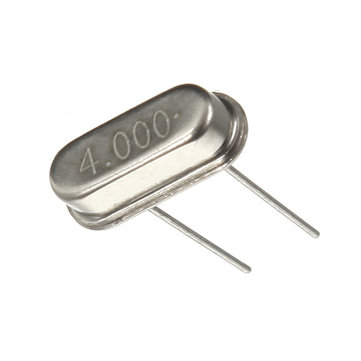
[12:55:04] <Jartza> http://upload.wikimedia.org/wikipedia/commons/6/6e/18MHZ_12MHZ_Crystal_110.jpg
[12:55:06] <RikusW> because ISP needs a clocking signal in the avr
[12:55:33] <Jartza> the device on left is crystal (resonator), the device on the right is oscillator (clock chip)
[12:55:46] <antto> okay, mine is the smaller one
[12:55:48] <antto> 16MHz
[12:56:04] <RikusW> antto: you can use another avr to generate a clock signal
[12:56:09] <antto> with two 22pF caps to ground
[12:56:16] <Jartza> yes
[12:56:25] <Jartza> but it works with fuse setting for external crystal
[12:56:32] <Jartza> external oscillator has separate power
[12:56:39] <Jartza> the device on the right
[12:56:51] <Jartza> you give it ground and clock and it gives clock signal out from one pin
[12:57:24] <antto> okay, so the external clock i need is something like a square wave on the XTAL1 pin?
[12:57:27] <N1njaneer> Sorry, keep getting pulled away :)
[12:57:42] <antto> and XTAL2 pin is left unconnected?
[12:58:07] <antto> and i get rid of the 16MHz resonator with the two caps?
[12:58:15] <N1njaneer> antto: A lower frequency (1Mhz or less) square-wave on the XTAL1 input should always help get you out of a jam if you accidentally set things to use external clock but the fuses aren't quite set correctly.
[12:58:33] <N1njaneer> At least you can generally set your ISP to a slow speed (100Khz) and recover.
[12:59:11] <Jartza> antto: yes, external clock. if you have other avr, create clock from that?
[12:59:26] <antto> crap.. ;]
[12:59:40] <antto> what have i done
[12:59:49] <antto> okay, at least i understand what i've done.. sort of
[13:00:51] <antto> Jartza is the external clock supposed to be like a square wave between 0V and VCC?
[13:01:46] <xorm> i would expect that to work
[13:02:02] <Jartza> antto: yes
[13:02:04] <xorm> idk what AVRs output as their CLKout but I suspect that it's that
[13:02:30] <antto> okay, so i need a square wave source of a few MHz..
[13:02:56] <Jartza> not really
[13:03:17] <Jartza> I've revived avr using 20kHz
[13:03:24] <Jartza> just need to set the programmer to _really_slow_
[13:03:34] <Jartza> like, avrdude -B250 or so :)
[13:03:42] <antto> i think the "slow" option on this usbasp is 1.5MHz
[13:04:01] <RikusW> avr clock must be at least 4 or 5 times the isp clock
[13:04:13] <Jartza> you can of course build the oscillator out of crystal...
[13:04:36] <antto> out of the 16MHz resonator i have?
[13:05:19] <Jartza> yes
[13:05:41] <Jartza> few caps, resistors and a transistor
[13:05:48] <Jartza> if my memory serves me right
[13:05:53] <Jartza> trying to find the bookmark
[13:06:49] <Jartza> http://circuit-diagram.hqew.net/Crystal-Oscillator-Circuit_5880.html
[13:06:50] <Jartza> there
[13:07:36] <N1njaneer> xorm: CLKOUT is a buffered version of the clock the system is running at. We use it regularly to pass 8-16Mhz of TTL on to certain TI LED drivers that need an external clock beyond the SPI bus
[13:09:01] <Jartza> http://en.wikipedia.org/wiki/Pierce_oscillator
[13:09:04] <Jartza> might even work with that
[13:09:08] <Jartza> I've never tried myself
[13:09:29] <RikusW> antto: got another working avr ?
[13:09:48] <antto> not exactly
[13:09:54] <antto> ;]
[13:10:27] <RikusW> signal generator ?
[13:10:33] <Jartza> got raspberry pi?
[13:10:41] <Jartza> oscilloscope? :)
[13:11:18] <RikusW> some usbasp got builtin clockgen iirc
[13:13:44] <antto> nope
[13:13:59] <antto> would it help if i use a parallel-port programmer instead of the usbasp?
[13:14:05] <antto> because i have one
[13:14:16] <N1njaneer> Wire up a microphone and whistle a 1Khz tone :)
[13:15:16] <antto> heh
[13:15:41] <RikusW> HVPP/SP would work
[13:16:06] <antto> SP?
[13:16:11] <RikusW> HVSP
[13:16:23] <antto> i don't have HV** ;P~
[13:16:52] <antto> but.. can i obtain some clock signal from the usbasp?
[13:16:59] <antto> by any chance
[13:17:05] <RikusW> do you have a scope ? to check the oscillator you'll be building ?
[13:17:10] <antto> nope
[13:17:20] <RikusW> frequency meter ?
[13:17:30] <antto> maybe, i'm not sure
[13:18:04] <RikusW> VDC might work, if there is a clock pin output on the usbasp it will measure VCC/2
[13:18:51] <RikusW> (the quick and dirty way of detecting a clock signal using a voltmeter)
[13:19:11] <antto> so, if i find some clock output on the usbasp - connect it to XTAL1, and use the parallel port programmer for the actual programming
[13:19:41] <RikusW> why not use usbasp ?
[13:20:01] <antto> where will i get the clock from then?
[13:21:01] <RikusW> there might be a clock output on one of the usbasp ic's pins
[13:21:07] <RikusW> not entirely sure
[13:22:03] <antto> the usbasp i got is probably a clone of a clone of a cloned clone of a usbasp ;P~
[13:22:09] <antto> iykwim
[13:22:11] <Jartza> what usbasp it is?
[13:22:17] <Jartza> I have several usbasps
[13:22:18] <antto> from elimex
[13:22:27] <Jartza> any pic of it?
[13:23:09] <antto> http://elimex.bg/userfiles/productlargeimages/product_18565.jpg
[13:27:07] <antto> tbh it smells like there won't be a clock source obtainable from there
[13:27:10] <antto> :/
[13:37:38] <Jartza> well, couldn't find clock out from my usbasp with scope :(
[13:39:00] <Jartza> antto: and it's the only chip you have? :(
[13:52:22] <antto> there are some pics but i have no clue about them
[13:52:31] <antto> ehm, PICs
[13:53:15] <RikusW> if you can load fw onto them it might work
[13:53:27] <RikusW> just enough to toggle a pin
[13:53:35] <RikusW> like port++;
[13:53:43] <RikusW> while(1) port++;
[13:54:02] <RikusW> bit0 will be highest frequency
[13:55:46] <antto> could i find an oscillator in some of the bits of electronics i got around?
[13:55:53] <antto> like my old VCR maybe?
[13:57:13] <RikusW> you could use the crystal, transistor and some other parts
[13:57:30] <RikusW> or crystal and logic inverter ic
[13:57:38] <RikusW> (not gates)
[13:57:57] <RikusW> google that, its pretty easy to build
[14:02:11] <Jartza> I already pasted few links
[14:11:54] <antto> okay
[14:12:17] <antto> well, btw.. in what setup do you use a resonator then?!
[14:12:56] <LeoNerd> Resonators are mostly "cheaper" but less accurate crystals, basically
[14:13:23] <antto> because the chip was initially set to use its internal clock, then i saw a number of schematics where a resonator (with two caps) was put between XTAL1 and XTAL2
[14:13:35] <antto> so i thought that THAT is "external clock"
[14:13:45] * antto scratches head..
[14:16:44] <Jartza> and some of the ceramic resonators have the caps built-in
[14:16:48] <Jartza> so less parts needed
[14:17:02] <Jartza> they have 3 legs, just connect the center leg to gnd
[14:18:35] <antto> okay but.. with what fuse settings do you use a resonator?
[14:18:50] <antto> if it's not with "ext. clock"
[14:18:55] <Jartza> it's "cyrstal"
[14:18:59] <Jartza> crystal
[14:19:11] * antto puts on 'o-o'
[14:19:30] <Jartza> I made that mix-up twice myself
[14:20:02] <antto> oh damn
[14:20:05] <Jartza> the strange thing was, using really really slow speeds and just bashing the avrdude on command line, I was actually able to set the fuses back to correct once
[14:20:14] <Jartza> I used something like -B4000 or something
[14:20:24] <LeoNerd> don't forget -b vs. -B
[14:20:35] <antto> there are 2 more options.. "Ext. LowFreq Crystal" and "Ext. Full-swing Crystal"
[14:20:38] <Jartza> and just kept repeating the command because I was frustrated :D
[14:20:45] <LeoNerd> One sets the avrdude <--> programmer baud rate, other sets programmer <--> AVR SCK rate. I always forget which
[14:21:08] <Jartza> I guess the -B is the latter
[14:21:37] <Jartza> antto: what was your chip?
[14:21:42] <antto> -B <bitclock> Specify JTAG/STK500v2 bit clock period (us).
[14:21:55] <antto> atmega328
[14:22:10] <Jartza> ok
[14:22:15] <antto> my low fuse is 0x60
[14:24:26] <Jartza> low freq crystal (I _think_) is something like kHz-grade
[14:24:31] <Jartza> 128kHz etc
[14:24:47] <antto> so i should have set it to ext full-swing?
[14:24:58] <antto> with that 16MHz resonator
[14:24:59] <Jartza> umm
[14:25:03] <Jartza> no
[14:25:08] <antto> o_o
[14:25:39] <antto> i give up ;]
[14:25:43] <Jartza> https://www.dropbox.com/s/fa3g96ool4pehzt/Screenshot%202015-01-26%2022.05.08.png?dl=0
[14:25:47] <Jartza> I would select the last one
[14:25:52] <Jartza> or the highlighted one
[14:26:09] <Jartza> no sorry
[14:26:10] <Jartza> argh
[14:26:20] <Jartza> there's toooooo many choises, granted
[14:27:24] <Jartza> yeah. it seems other parts use different terminology
[14:27:48] <Jartza> yeah. you need the full swing ext.
[14:28:43] <RikusW> antto: just set lowfuse to 0xFF
[14:29:05] <RikusW> 0x7F if you need CKDIV8
[14:29:50] <Jartza> isn't that wrong for crystal which is not oscillator? :)
[14:30:07] <RikusW> that is what I use with a 16MHz crystal
[14:30:25] <Jartza> oh
[14:30:45] <RikusW> external crystal 8Mhz and up
[14:31:44] <RikusW> seems to be the same on quite a few avrs
[14:32:35] <Jartza> I understood you need to select full swing for everything over 8MHz
[14:32:50] <antto> well, i'll have to leave the atmega to "ext clock" anyway
[14:33:30] <antto> because it's gonna be hooked up with an enc28j60 which provides CLKout
[14:34:03] <antto> hm..
[14:35:34] <antto> i wonder.. would it be enough to hook up the enc28j60 with vcc and gnd, and a resonator, for it to output CLKout which is usable in my case?
[14:35:39] <RikusW> then get the other chip up and running to provide the clock ?
[14:35:49] <RikusW> its possible
[14:36:08] <RikusW> read its datasheet to be sure
[14:36:32] <antto> but it requires 25MHz..
[14:36:57] <antto> that's too high for the atmega328 according to the datasheet
[14:37:05] <antto> bleh ;]
[14:44:11] <Jartza> ohh
[14:44:18] <Jartza> the "full swing" has something to do with the capacitors
[14:51:34] <RikusW> full swing means what it says
[14:51:47] <LeoNerd> It's the opposite of light jazz
[14:51:51] <LeoNerd> <.< >.>
[14:52:04] <N1njaneer> Jartza: Unless you are doing power-critical consumption for battery stuff, ALWAYS ENABLE FULL SWING
[14:52:06] <RikusW> the XT2 will give more volts to the crystal
[14:52:15] <RikusW> and use more power as a result
[14:52:31] <RikusW> its for use in noisy environments
[14:52:39] <N1njaneer> We have had things returned back to us because the parts were not running in-spec (ATMEGA128 vs ATMEGA128A) because that fuse was not set.
[14:53:21] <N1njaneer> The silicon actually had measurable differences between the 128 and 128A revisions for items that were not indicated in the errata, and I'd sent this information back to Atmel.
[14:53:21] <Jartza> yes, there seems to be suggestion that always enable full swing with 8MHz and more
[14:53:43] <N1njaneer> Since we've been enabling full-swing on all parts that feature it, we've never gotten anything back with that problem.
[14:54:19] <N1njaneer> Rikus: Yeah, definately also for the noisy environments.
[14:55:06] <N1njaneer> The problem we saw was that the 16Mhz crystal was actually not running at exactly 16Mhz without the FULL SWING fuse set. This primarily caused the serial ports to get garbage on them since the baud rates were drifting from where they were supposed to be.
[14:55:37] <N1njaneer> Anyhow, some suggestions based on our experiences here. Let our mistakes help you not make them!
[14:56:09] <Jartza> but then again, the suggested 0xFF selects "external crystal oscillator" and not "external crystal full swing"
[14:56:30] <RikusW> I've not had problems with 16MHz and 0xFF as lowfuse yet
[14:56:51] <Jartza> but you're using oscillator, not crystal? :)
[14:56:53] <RikusW> it is specifically for >= 8MHz
[14:57:01] <RikusW> I used a crystal
[14:57:24] <RikusW> a 2 pin type
[14:57:39] <Jartza> but that fuse setting (at least according to fuse calculator) is for crystal oscillator
[14:57:49] <RikusW> https://sites.google.com/site/megau2s/
[14:57:54] <RikusW> that one, low profile
[14:58:30] <Jartza> maybe I've understood something wrong then?
[14:58:40] <Jartza> http://www.mas-oy.com/uploads/images/XO.jpg
[14:58:45] <Jartza> that's "crystal oscillator"?
[14:59:03] <Jartza> http://img.banggood.com/thumb/view/upload/SKU033936/20120621120759656.JPG
[14:59:10] <Jartza> and this is "crystal" or "crystal resonator"?
[14:59:47] <Jartza> the oscillator needs VCC and GND and gives clock out from one pin
[15:00:07] <Jartza> whereas crystal/resonator is connected to 2 pins and caps to gnd
[15:00:33] <Jartza> ?
[15:00:46] <RikusW> seems atmel means crystal osc as 2pin crystal...
[15:00:52] <RikusW> it works just fine for me
[15:01:46] <RikusW> I used mega32u2 with lowfuse = 0xFF, and that seems to be the exact same setting as mega328
[15:02:29] <RikusW> I haven'
[15:02:38] <RikusW> t even had problems with baudrates
[15:02:53] <RikusW> even at 115,2k
[15:03:59] <Jartza> then what's the difference with 0x7F?
[15:04:08] <Jartza> that's >8Mhz ext crystal full swing :)
[15:04:22] <RikusW> 0x7F enables CKDIV8
[15:04:33] <RikusW> on some avrs
[15:04:44] <RikusW> read the datasheet to be sure
[15:06:44] <Jartza> oops, meant 0xF7
[15:07:35] <aandrew> does anyone have some documentation on the IAR intrinsic __DataToR0ByteToSPMCR_SPM() ?
[15:07:53] <Jartza> I don't quite understand the difference now with "external crystal" and "external crystal oscillator" then
[15:08:00] <Jartza> if crystal works with both settings
[15:08:10] <aandrew> I'm trying to convert this bootloader over to avr-libc but don't understand what this function is doing
[15:08:21] <Jartza> how do you use the "crystal oscillator" then? connect it as "external clock"?
[15:09:18] <aandrew> it's being invoked as __DataToR0ByteToSPMCR_SPM(0, 0x11) which is supposed to be clearing the temporary page buffer
[15:09:59] <N1njaneer> Jartza: I think they are meaning "raw quartz" vs "TTL clock-in-a-can"
[15:10:38] <N1njaneer> The raw quartz needs the resonance caps and additional parameters from inside the micro to oscillate correctly. The TTL clock obviously only needs to be an input on XTAL1 and XTAL2 is free for GPIO, etc.
[15:11:25] <RikusW> Jartza: for 4 pin ones that take vcc - probably
[15:11:42] <RikusW> aandrew: read the instruction set SPM docs
[15:12:40] <aandrew> I'm looking at the datasheet
[15:12:43] <RikusW> aandrew: it probably puts the data into R0 and calls SPM
[15:12:56] <Jartza> N1njaneer: yeah, I think so too. So to use these "4-legged beasts" I need external clock selection and for crystal the "crystal" or "crystal oscillator" :)
[15:13:00] <Jartza> which seem to be the same thing
[15:13:05] <RikusW> you'll need the bootloader section and the instruction set reference
[15:13:07] <Jartza> except some have "full swing" and some don't
[15:13:18] <aandrew> but I don't see an equivalent avr-libc function, which is why I was asking
[15:13:50] <RikusW> aandrew: in the avrlibc docs you should find something equivalent
[15:14:21] <RikusW> SPM is used to write to flash
[15:15:22] <Jartza> well. the naming just confused me then.
[15:15:23] <aandrew> RikusW: yes, avr/boot.h has all the spm-related stuff
[15:15:29] <aandrew> but nothing specifically clearing the temporary page buffer
[15:15:31] <RikusW> file:///usr/share/doc/avr-libc/avr-libc-user-manual/group__avr__boot.html
[15:15:39] <aandrew> at least not on the online doc
[15:15:43] <aandrew> http://www.nongnu.org/avr-libc/user-manual/group__avr__boot.html
[15:15:56] <Jartza> because I've heard terms "crystal" or "crystal resonator" from the 2-legged beasts and "crystal oscillator" meaning the 4-legged version
[15:16:08] <Jartza> might be that the terminology isn't universal :)
[15:16:24] <Jartza> good to know
[15:17:00] <N1njaneer> aandrew: Just write new contents to the page buffer.
[15:17:05] <RikusW> aandrew: write some inline asm ?
[15:17:05] <aandrew> N1njaneer: that's what I'm doing
[15:17:14] <aandrew> I don't think it's important, I was just wondering if I was blind of what
[15:17:19] <aandrew> RikusW: indeed
[15:17:21] <N1njaneer> aandrew: No reason to have to explicitly clear it :)
[15:18:06] <RikusW> in my experience writing to flash is tricky
[15:18:23] <RikusW> it must be done exactly by the book or it will fail....
[15:19:21] <aandrew> *nods*
[15:19:31] <aandrew> the clearing of the temporary page does not appear to be required by teh doc
[15:19:50] <aandrew> I'm taking AVR112 (i2c bootloader) and porting it to avr-libc for attin25/45/85
[15:20:31] <N1njaneer> RikusW: I have written a handful of bootloaders for AVR over the years - generally haven't had much difficulty with it. Just have to pay attention to flash ready states and make sure you're clearing the flash pages to be written to. :)
[15:20:48] <RikusW> and the Z pointer...
[15:21:05] <N1njaneer> Do it in C and it's very straight-forward.
[15:21:17] <RikusW> seems it must point to start of page to work
[15:21:25] <N1njaneer> There are a lot of helper functions as well in avr/boot.h
[15:21:26] * RikusW used asm
[15:23:10] <N1njaneer> My suggestion is to write it in C, no optimizations, and see if it all works correctly. Then turn all optimizations up to full and again see if it all works correctly. The check it for size. If it's small enough, then you're done. If there's a compelling reason to have to make it smaller, look at the .lss file and see where your code is bloating out, and attempt to hand-optimize sections to squeeze
[15:23:11] <N1njaneer> it down more.
[15:23:21] <N1njaneer> Just don't preemptively optimize, else you'd just wasting time. :)
[15:24:50] <N1njaneer> Since you're restricted to certain bootloader size allocations anyhow in the chip, you can pretty quickly approximate if you even think you can make it to the next size down with hand-optimized assembler. You may quickly find out that you probably can't or there's not a compelling reason to. But just my two cents of getting stuff banged out quickly and reliably in a production environment.
[15:24:58] <RikusW> well, I did fit usb CDC and the bootloader into 2k
[15:25:42] <RikusW> CDC took 800 bytes
[15:26:50] <aandrew> yay it builds
[15:29:34] <N1njaneer> Awesome!
[15:30:59] <aandrew> now to figure out where the default linker file is and adjust it so I can have a bootloadable application
[15:32:48] <N1njaneer> aandrew: Point of order here -- be aware that AVR instruction words are each two bytes, so pay careful attention to the actual hex address you want to place things at. You may have to double or halve it, depending on what youre adoing.
[15:32:52] <N1njaneer> +doing
[15:33:25] <N1njaneer> aandrew: Also make sure to correctly flip the vector interrupt table when entering or leaving the bootloader as necessary.
[15:33:32] <aandrew> yep
[15:33:48] <N1njaneer> Little gotchas that can drive people mad for hours. :)
[15:33:56] <aandrew> agreed
[15:34:11] <aandrew> appreciate the input, it's these things that I tend to forget too
[15:36:04] <aandrew> hm, does avr-gcc not use linker files?
[15:36:19] <aandrew> searching the crosspack directory tree for '*.ld' doesn't reveal anything
[15:43:50] <aandrew> ah, xn files
[15:51:48] <aandrew> hm
[15:52:38] <aandrew> N1njaneer: in AVR, how do you reassign the interrupt vectors? they seem to be in program memory and that's that
[15:52:41] <aandrew> I don't see a remap method
[15:53:54] <aandrew> I mean the bootloader code just preserves the reset vector so it always jumps to the bootloader but otherwise allows reprogramming of sector zero (where the table is)
[15:54:02] <aandrew> so in that case I think I have it covered
[15:54:09] <aandrew> I just can't use interrupts in the bootloader, which I already don't do
[15:55:16] <davor> I've got a question regarding the 328's datasheet. under fuses, it says that 0 is programmed, and 1 is unprogrammed. elsewhere SUT0 and 1 bits are described with 00, 01, 10 and 11 combinations. does 1 there correspond to 1 under fuses, or does it correspond to programmed (0)?
[15:55:20] <RikusW> there are a register for doing it
[15:55:33] <davor> specifically pages 283 and 42
[15:55:35] <davor> *34
[15:55:49] <davor> pages 283 and 34
[15:56:08] <RikusW> davor: 0 probably means programmed
[15:56:23] <RikusW> since the default state is 1
[15:57:48] <davor> so if I wanted to program it for fast rising power, which corresponds to SUT1 = 0 and SUT0 = 1, I would actually write a 1 under SUT1 and a 0 under SUT0 in the low fuse?
[15:58:10] <N1njaneer> aandrew: You need to make sure to pay attention to how IVSEL is set in the MCUCR register. See page 65 (Section 12.4) on the ATMEGA328 datasheet
[16:00:18] <malinus> aandrew: you can't remap the interrupt vectors. How would that even work?
[16:00:39] <N1njaneer> Malinus: Of course you can remap the interrupt vectors :)
[16:00:39] <malinus> is that possible in x86?
[16:01:06] <malinus> N1njaneer: explain please
[16:01:23] <davor> hm, according to the datasheet, the bits written on page 34 for a particular mode are the ones that should be written in the low fuse. so I can't figure out how Arduino has 11 written for SUT0 and SUT1, when the mode corresponding to 11 is "reserved"
[16:01:43] <N1njaneer> malinus: It's necessary if you use interrupts in your bootloader, because your normal interrupt table will be wiped out when you are reprogramming the beginning of the application flash. :)
[16:02:44] <N1njaneer> malinus: IVSEL allows you to remap where the AVR looks for the interrupt vectors. If you are writing a bootloader that uses interrupts, you set IVSEL and then the interrupt vector table used will appear near the top of memory at the beginning of the bootloader segments.
[16:02:45] <malinus> N1njaneer: I thought the bootlader could start after the interrupt table, and you could just flash after it?
[16:02:50] <aandrew> N1njaneer: no IVSEL in tiny25 :-)
[16:03:07] <malinus> N1njaneer: oh I didn't know, thanks a lot.
[16:03:12] <malinus> that's pretty neat
[16:03:19] <N1njaneer> aandews: Oh I'm sorry, I mixed up your processor with davor :)
[16:03:29] <N1njaneer> I pulled the 328 datasheet :D
[16:03:36] <malinus> thanks for explaining N1njaneer
[16:04:17] <N1njaneer> Sure.
[16:06:09] <RikusW> davor: SUT1 = 1 will probably mean a 1 in the fuse
[16:06:34] <RikusW> for mega328 for example 0xFF means external crystal
[16:06:46] <RikusW> and then both SUT bits are 1
[16:07:10] <RikusW> atmel docs aren't always entirely clear....
[16:07:31] <davor> ah cheers! must've missed it
[16:07:33] <RikusW> have a look at the xml part files that comes with Atmel studio.
[16:07:48] <davor> ah thanks
[16:07:53] <RikusW> they list valid fuse values
[16:08:11] <aandrew> how the hell is this bootloader 0x388 bytes long, that's enormous given that the entire chip is only 0x3ff bytes
[16:08:49] <RikusW> aandrew: which chip ?
[16:09:16] <aandrew> attiny25
[16:09:37] <RikusW> 0x400 is 1k
[16:09:52] <RikusW> unless you're using word addresses
[16:10:04] <LeoNerd> Why are you putting a bootloader on a 'tiny25 anyway?
[16:13:16] <aandrew> this will be embedded in epoxy in a pipe... difficult to update in that form
[16:13:24] <LeoNerd> Ahh
[16:13:50] <LeoNerd> Yeah, I'm planning a two-chip board with an 84 and 2313. I want to see if I can ISP the 2313 via the 84 over nRF wireless
[16:17:01] <aandrew> I figured I could get a little i2c bootloader into 256 bytes of program memory
[16:17:07] <aandrew> I might have to pare this down a bit more
[16:17:17] <aandrew> I honestly wasn't expecting the bootloader to be so huge
[16:17:34] <LeoNerd> What's the general technique for bootloaders on tiny chips?
[16:17:39] <LeoNerd> They lack a real hardware support for it
[16:17:50] <aandrew> AVR112 spells out one method
[16:18:04] <LeoNerd> Ooh *goes to read*
[16:18:07] <aandrew> basically your bootloader takes over teh reset vector and sits at the end of flash
[16:18:25] <aandrew> then reprogram operations "protect" the reset vector but allow programming of everything else, up to the start of the bootloader region
[16:18:38] <aandrew> so every reset jumps to the bootloader and if the bootloder is happy, jumps to the application
[16:19:03] <LeoNerd> Ooooh
[16:19:06] <davor> bit of a stupid question, but regarding fuses, the "leftmost" bit is bit no.7 and the "rightmost" bit is bit no.0 right?
[16:19:06] <LeoNerd> reset vector :)
[16:19:25] <LeoNerd> I was wondering otherwise how to convince the compiler to make the real firmware to position taking account of the loader
[16:19:51] <aandrew> yep they cheat
[16:20:05] <aandrew> reduce flash size by 1 page and don't worry about it :-)
[16:20:33] <LeoNerd> Nice
[16:20:36] <N1njaneer> davor: Generally, yes, as a left shift is *2 and right shift is /2
[16:20:49] <davor> cheers
[16:20:59] <davor> makes sense
[16:21:00] * N1njaneer cheers
[16:21:05] <davor> ha :)
[16:21:56] <aandrew> aha
[16:22:07] <aandrew> USI_TWI_SLAVE_Process_Overflow_Condition is one of the culprits... 0x166 bytes
[16:22:21] <aandrew> that's most of it in fact
[16:22:57] <aandrew> that's a shitty function name. overflow is an error condition, they use it as "data buffer full"
[16:23:02] <malinus> davor: usually the lsb is 0, yes.
[16:23:33] <LeoNerd> I wonder if I can use this technique to do over-wireless firmware upgrade then
[16:23:36] <LeoNerd> Or something similar
[16:24:12] <N1njaneer> LeoNerd: Or just consider using a processor that already has OTA firmware upgrade capabilities :)
[16:24:17] <N1njaneer> Might make life simpler.
[16:24:50] <LeoNerd> I'm more-or-less committed to using nRF24L01s now
[16:24:55] <LeoNerd> I'm building parts of a larger system
[16:33:38] <Jartza> aandrew: ooh, you writing attiny bootlaodeer too? :)
[16:33:43] <Jartza> or bootloader, even
[16:34:10] <N1njaneer> Nordic makes some good parts. I have designed an nRF51822 in to a recent design we're currently working on.
[16:35:03] <N1njaneer> LeoNerd: Why not just us an nRF51x22 and just drop the 2313?
[16:35:16] <N1njaneer> Just use a single part.
[16:37:21] <LeoNerd> N1njaneer: oooh.. that looks quite cute
[16:37:45] <N1njaneer> It's a nice part. Cortex M0+ ARM, lots of GPIO, all completely pin-mappable too!
[16:38:01] <N1njaneer> And their full BLE stack takes a lot of the heavy lifting out of app development.
[16:40:11] <LeoNerd> Hmmm
[16:40:31] <LeoNerd> But can I buy it for, like.. £2? I can get an nRF and a tiny84 for £1 each
[16:41:33] <N1njaneer> nrf51822's are about $4.11/ea single quantity here it the US, so I suspect yes :)
[16:42:05] <LeoNerd> On a board though? I mean, I can get those little boards with an nRF24L01 and all the RF frontend and board antenna on it
[16:42:32] <N1njaneer> Not sure, you'd have to look around. :)
[16:42:36] <LeoNerd> Hmmm
[16:43:14] <N1njaneer> I do all boards here from scratch so it's not an issue, but if you're looking for a more finished modular solution you'll need to see what's out there
[16:43:49] <LeoNerd> Hmm. I just don't overly fancy doing 2.4GHz radio work.
[16:45:28] <N1njaneer> It's honestly not too bad, and Nordic has some really great guidelines and samples for dealing with the antenna portions.
[16:55:28] <N1njaneer> I get to live in the jungles of horrible MSP430 code-porting today.
[17:51:10] <Casper> rue_shop2: in canada, is it the NEC code that is active? or another one? need to find the article number for the wire gauge vs breaker size for house wiring
[19:09:06] * specing turns OndraSter|off back on
[19:26:25] <hypermagic> hello my friends
[19:26:32] <hypermagic> what are you creating ?
[19:28:11] <Lambda-Aurigae> just had a funzie idea on the way home from work.
[19:28:32] <Lambda-Aurigae> digging out a couple of old laptops and putting linux on them to test a theory.
[19:29:37] <Lambda-Aurigae> gonna try to make a chicken-n-egg programmer for a laptop with no serial or parallel ports.
[19:30:26] <Lambda-Aurigae> through the SD card slot.
[19:37:40] <hypermagic> labmdat works, already tried it :)
[19:37:47] <hypermagic> Lambda-Aurigae
[19:37:53] <Lambda-Aurigae> oh?
[19:38:16] <hypermagic> you can try damn-small linux on ancient laptop, it is min 50MB
[19:38:32] <Lambda-Aurigae> installing debian on them.
[19:38:41] <hypermagic> tried it on 64MB SSD and it works with 256MB ram with graphical desktop
[19:38:50] <hypermagic> (even with 128MB)
[19:39:27] <Lambda-Aurigae> yeah, think you don't understand what I'm trying to do.
[19:39:32] <hypermagic> old laptops have parallel port
[19:39:34] <Lambda-Aurigae> not running the linux on the SD card.
[19:39:48] <Lambda-Aurigae> using the sd card slot to connect to the AVR.
[19:39:56] <hypermagic> hm
[19:40:05] <hackvana> You're trying to bring out the SD card lines from the laptop, in order to program an AVR
[19:40:07] <hypermagic> you mean the SD card computer?
[19:40:07] <hypermagic> ;>
[19:40:16] <Lambda-Aurigae> bingo.
[19:40:22] <hypermagic> that s just useless because it lacks io ports and display port
[19:40:27] <Lambda-Aurigae> bring out sd card lines to connect and program AVR.
[19:40:47] <hackvana> You typically don't get much control over those lines
[19:40:58] <Lambda-Aurigae> that's what I'm trying to work on.
[19:41:04] <hypermagic> http://hackaday.com/2013/08/12/hacking-transcend-wifi-sd-cards/
[19:41:11] <hypermagic> i wuld not pay a dime for this crap
[19:41:17] <Lambda-Aurigae> I have 3 laptops with sd card slots in them.
[19:41:40] <Lambda-Aurigae> one is usb connected internally. the other two are pci connected through the southbridge chip.
[19:43:22] <dj_pi> is there a way to float gpio pins for avr series uC?
[19:43:32] <Lambda-Aurigae> dj_pi, set them as inputs.
[19:43:54] <dj_pi> ah...ok...didn't think of it that way
[19:43:57] <dj_pi> but makes sense
[19:44:01] <dj_pi> i will try this...thanks!
[19:44:07] <Lambda-Aurigae> and make sure pullups are turned off.
[19:44:45] <dj_pi> yeah...thanks Lambda-Aurigae
[19:45:06] <Lambda-Aurigae> happy to be of assistance.
[19:47:03] <hypermagic> dj_pi, yes
[19:47:06] <hypermagic> tristate
[19:47:52] <dj_pi> is there a function in the atmel api that i can call to do this?
[19:47:58] <dj_pi> specifically...i'm looking in pio.h
[19:48:34] <dj_pi> right now i'm calling the gpio_configure_pin option and passing it the flags that i want
[19:48:46] <hypermagic> /* set PORTB for output*/
[19:48:46] <hypermagic> DDRB = 0xFF;
[19:49:11] <hypermagic> we are talking about setting a port regitser bit...
[19:49:18] <Lambda-Aurigae> atmel api?
[19:49:32] <dj_pi> *atmel studio
[19:50:04] <dj_pi> i'm using the ASF
[19:50:32] <Lambda-Aurigae> aahh...there is a tristate mode.
[19:50:41] <Lambda-Aurigae> I know nothing about ASF...doesn't work on linux.
[19:51:03] <Lambda-Aurigae> but for tristate, you set the DDxn to 0, PORTxn to 1, and PUD to 1
[19:51:04] <dj_pi> ah....yeah....i'm in windows for this project
[19:51:39] <Lambda-Aurigae> or DDxn to 0, PORTxn to 0 and PUD is irrelevant.
[19:51:48] <Lambda-Aurigae> right in the datasheet.
[19:51:55] <dj_pi> looking now....
[19:52:00] <dj_pi> thanks for the help
[19:52:09] <Lambda-Aurigae> for the atmega1284p it is section 14.2.3
[19:54:01] <N1njaneer> Yes, you want PORTxn to be 0 else you are weakly-biasing with the pull-up resistor :)
[19:54:24] <Lambda-Aurigae> so, as I said earlier, set the pin to input with no pullup resistor.
[19:54:39] <N1njaneer> Yup.
[19:58:27] <hypermagic> fkin octopusdicks
[19:58:43] <hypermagic> i have mounted avr stuff on / and no way unmounting, and it does not work
[19:58:45] <Lambda-Aurigae> kinky.
[19:59:03] <Lambda-Aurigae> oops.
[19:59:09] <Lambda-Aurigae> why can't you unmount it?
[19:59:22] <hypermagic> it starts and exits umount with not errors
[19:59:30] <hypermagic> and apparently does nothing
[20:00:04] <hypermagic> the image file had a /avr directory, and i already had a/avr directory on /
[20:01:53] <Lambda-Aurigae> if you mounted it on / then it sounds like you hosed the system. might have to reboot as none of your commands will be accessable.
[20:02:15] <Lambda-Aurigae> only things already resident in memory will work properly.
[20:19:52] <Brando753> Hey guys I have a project I want to use debug wire on for debugging, I understand once the debug wire fuse is set the RESET line becomes the DW line and that prevents ISP from working, is there a way in linux to deactivate the debugwire fuse through debugwire?
[20:20:29] <Tom_itx> you would think so
[20:20:38] <Lambda-Aurigae> Brando753, have you checked the datasheet? what chip?
[20:24:19] <Brando753> Attiny88
[20:24:57] <hypermagic> totally lost all my avr sources i need to find them again after 3 months
[20:25:08] <Lambda-Aurigae> well, looks like you can not write fuses with debugwire.
[20:25:17] <Lambda-Aurigae> so, the only to recover from debugwire is HVSP.
[20:25:31] <Brando753> which is highly impractical when debugging a board
[20:25:41] <Brando753> because HVSP needs a 12V line
[20:25:59] <Lambda-Aurigae> and a bit of a change in the programming specifications.
[20:26:04] <Lambda-Aurigae> err..programming protocol.
[20:27:00] <Brando753> But my understanding was that while debugWire can not change fuses it can shut itself off so you can ISP again
[20:27:39] <Lambda-Aurigae> it seems you can turn on debugwire on and off on the fly without setting the fuse...I think.
[20:28:30] <Lambda-Aurigae> hmmm...looks like it has to be done through atmel studio on the fly.
[20:28:51] <Brando753> But I figure there has to be a way to do it on linux
[20:28:53] <hypermagic> where you keep your sources?
[20:29:06] <hypermagic> on dvds backuped on your desk ?
[20:29:17] <Lambda-Aurigae> hypermagic, on an external harddrive.
[20:29:29] <hypermagic> what if that dies?
[20:30:26] <Brando753> hypermagic: thats why you have redundancy
[20:30:30] <Lambda-Aurigae> http://www.avrfreaks.net/forum/debugwire-programming
[20:30:36] <Lambda-Aurigae> read through that...specially #11
[20:30:43] <Brando753> alright looking
[20:31:14] <Lambda-Aurigae> there is a way to make it disable debugwire from within debugwire with some kind of reset.
[20:33:56] <Lambda-Aurigae> I'm not sure on the details on how to do the partial reset...that's probably in the debugwire documentation.
[20:34:11] <Lambda-Aurigae> I didn't know there was a linux debugwire interface program that was fully functional though.
[20:34:21] <Lambda-Aurigae> anyhow,,,have to go. wife is calling me to bed.
[20:34:47] <Brando753> Good night o/ Thanks for the help
[21:48:07] <hypermagic> extra failsafe is necessary for mission critical heating control applications ?
[21:48:42] <hypermagic> like using a hardware monostable multivibrator that must be constantly fed with clock to keep heater alive ?