Back
[00:00:36] <rue_bed> wow, cool chip
[00:00:38] <Shavik> http://www.mouser.com/ProductDetail/Silicon-Labs/Si8662BC-B-IS1/?qs=sGAEpiMZZMssyD0wnx%2fymMCNsiFGJQT9WiQj3E9s2AM%3d
[00:00:40] <Shavik> holy cow
[00:00:40] <rue_bed> or module
[00:00:48] <rue_bed> proly costs a lot
[00:00:50] <Shavik> 3.75 kV isolation
[00:01:15] <Shavik> UL1069 for nurse call systems only requires 1500V
[00:02:27] <Shavik> They have 5kV ones as well. impressive
[00:07:18] <Shavik> rue_bed. you were right.
http://www.linear.com/purchase/LTM2883 - $17-20 ish
[00:07:39] <Shavik> The one from mouser isn't nearly as fancy. but is only $2-5 depending on iso V
[00:09:00] <Shavik> http://www.ti.com/lit/an/slla067b/slla067b.pdf interesting read from TI on board communication methods just in case anyone else wanted to check it out
[00:17:49] <Shavik> Just "discovered" this.
http://en.wikipedia.org/wiki/Single_Connector_Attachment
[00:20:42] <Casper> ... nobody want to buy me this lens for xmas :(
[00:21:12] <Casper> http://www.adencamera.com/product-overviewer.asp?ProdID=5145&Category=7 <=== is that really too much to ask? or is everyone too cheap? :D
[00:21:33] <Shavik> List price is outrageous. Glad their price is so much lower
[00:22:15] <Casper> yeah... I'ld like to see the difference in image quality between it and a standard lens...
[00:22:26] <Casper> I think the only reason why it's that expensive is due to the controls
[00:43:21] <ph30n1x> hello guys need help
[00:44:15] <ph30n1x> Can anybody write a c-code for calculator function is to add two 8 character numbers
[00:46:44] <ph30n1x> i have written a code to interface keypad and display key pressed in serial monitor but have difficulties in storing numerals in a array
[00:49:33] <ph30n1x> then covert it into integer and detect a operator (+,-,*./) and then again hold selected operator in a location and again scan and store character in array 2 untill = is pressed and then covert the 2nd array into integer and do the selected operation and show the result
[00:50:36] <ph30n1x> hello people please help me
[00:51:51] <Casper> sorry, I don'T do asm, I find the tradeoff to be too expensive for my time vs the small space I'ld save vs how unmaintenable asm is
[00:52:13] <Casper> wait more, maybe someone that use asm will pop in tonight
[00:52:25] <ph30n1x> asm means?
[00:53:51] <ph30n1x> need code in Embedded C language
[00:55:34] <Casper> oh wait...
[00:55:39] <Casper> I totally misread it...
[00:55:54] <Casper> you want C.. not asm... woops
[00:56:00] <Casper> see, I should be in bed
[00:56:04] <Casper> nite
[00:56:15] <ph30n1x> Its morning here
[00:56:23] <ph30n1x> in India
[00:56:24] <Casper> 1:36... am...
[00:56:30] <Casper> working today of course
[00:56:36] <ph30n1x> 12pm
[00:56:38] <Shavik> 12:30 am here :) get to bed casper
[00:57:00] <ph30n1x> how was thanksgiving?
[00:57:00] <Casper> shavik: yeah, now I'm starting to be sleepy (sleep issue here)
[00:57:11] <Casper> wrong date in canada :D
[00:58:13] <Casper> I was hopping that a sale would come online...
[00:58:25] <Casper> ... but I guess they will only update the price when the store will open today...
[00:58:42] <Casper> I want to buy a lense for my camera
[00:58:49] <Shavik> or a car
[00:59:13] <Casper> ah just read some small characters...
[00:59:18] <Casper> won't be in special...
[01:01:17] <Shavik> http://www.ti.com/lit/ds/symlink/tca4311a.pdf
[01:01:51] <Shavik> "The TCA4311A is a hot-swappable I2C bus buffer that supports I/O card insertion into a live backplane to 5.5 Vwithout corruption of the data and clock busses."
[01:02:00] <Shavik> that sounds like exactly what i need
[01:15:46] <ph30n1x> guys any help?
[01:15:53] <Shavik> not sure. :( sorry
[01:15:53] <ph30n1x> on that code?
[01:15:57] <Shavik> or i would
[01:16:07] <ph30n1x> you would?
[01:16:13] <Shavik> if I knew
[01:16:25] <ph30n1x> okay
[01:16:47] <ph30n1x> you guys here are coders or circuit builders?
[01:17:23] <ph30n1x> whats your expertise Shavik?
[01:17:31] <Shavik> Both technically
[01:17:42] <Shavik> But like Casper. I'm basically asleep in my chair
[01:17:55] <Shavik> Can't really help tonight on code
[01:18:03] <Shavik> I'm just reading datasheets on chips right now
[01:18:10] <Shavik> I'm reading this
http://www.ti.com/lit/ds/symlink/tca4311a.pdf
[01:18:24] <ph30n1x> its okay if you can later some time?
[01:18:48] <ph30n1x> let me rephrase it
[01:19:49] <ph30n1x> later if you are free, can you send me the code to my e-mail?
[01:19:56] <ph30n1x> is it possible?
[01:21:23] <ph30n1x> i saw that datasheet. what are the applications of that Bus Buffers?
[01:21:40] <ph30n1x> any purticular project?
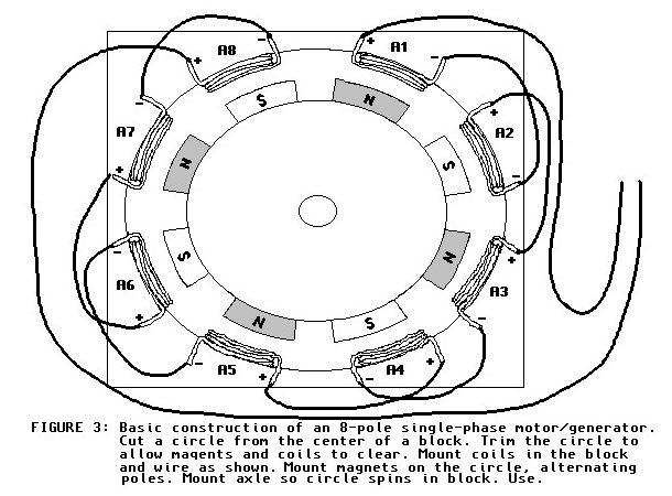
[05:06:42] <bitd> I am trying to understand how generators work. I found a pretty good example:
https://web.stanford.edu/~hydrobay/lookat/big/pmg/fnfig-03.jpg Now my question is, could I lower the voltage by wiring the generator in multiple phases?
[07:07:47] <Tom_itx> bitd,
http://www.thebackshed.com/Windmill/FPRewire.asp
[07:39:10] <LeoNerd> Hrm.. wonder if I should look into buying a tiny841 devboard.. Are they nice? It looks to be a lot more featureful than a tiny84
[07:39:16] <LeoNerd> Not one but /two/ UARTs
[08:16:41] <bitd> Tom_itx, thank you for that link. I was AFK. Reading it now.
[08:28:49] <HyrulianHero> Good morning central time :)
[08:28:56] <HyrulianHero> and hello #avr
[08:46:12] <hypermagic> hello my friends
[08:46:49] <twnqx> good afternoon from work :(
[08:50:29] <bitd> hello hypermagic
[08:56:08] <bitd> Tom_itx, "We are going to rewire the stator into shorter strings to reduce the voltage, and then connect these strings in parallel to increase the current."
[08:56:25] <bitd> Thats what I thought, someone told me that wasnt the case.
[08:58:31] <hypermagic> anybody know where to get a tunnel diode?
[08:58:43] <hypermagic> like the 1n3716
[09:13:48] <twnqx> digikey? :>
[09:14:01] <Lambda_Aurigae> farnell, digikey, arrow
[09:24:02] <hypermagic> i can't seem to find tunnel diode, esaki diode anywhere
[09:29:18] <Lambda_Aurigae> hmm.. 25% off any order at www.schmatrboard.com with the code Thanksgiving
[09:46:05] <twnqx> i want a pi or similar with PoE (without extra shield etc)
[09:46:19] <Lambda_Aurigae> well, the rPI doesn't do PoE
[09:46:27] <Lambda_Aurigae> you would need an adapter inline for that.
[09:46:52] <Lambda_Aurigae> the new rPI doesn't even back power through the USB ports anymore, which is a good thing.
[09:47:39] <Lambda_Aurigae> http://www.adafruit.com/products/435?gclid=COGlprLOncICFUQLMgod9QUAJg
[09:47:54] <Lambda_Aurigae> injector set...but that's not gonna quite work so well with real PoE
[09:54:59] <twnqx> no need for that, i have a poe capable switch
[09:56:21] <Lambda_Aurigae> I'm not seeing anything like the rPI or beaglebone that does real PoE.
[09:57:13] <twnqx> yeah :/
[09:57:23] <twnqx> i found 1-2 experimental boards
[09:57:32] <twnqx> but no cases for those, of course
[10:09:33] <Shavik> I'm looking at the Arduino Leonardo schematic and it has a 5.6v 1W Zener diode between usb 5v and GND. What is the purpose of this diode? If the voltage goes above 5.6v it has a lower resistance to ground as to not overvolt the components?
[10:10:56] <LeoNerd> That sounds plausible
[10:11:50] <Shavik> Just not had really experience with them. I feel I'm still lacking some understanding but I guess that's enough
[10:13:09] <Lambda_Aurigae> the zener diode is likely backwards in the circuit
[10:13:18] <Lambda_Aurigae> so it doesn't conduct until the voltage reaches 5.6V.
[10:13:27] <Lambda_Aurigae> at which point it breaks down and conducts.
[10:13:38] <Lambda_Aurigae> it is the simplest linear voltage regulator.
[10:14:13] <Lambda_Aurigae> once the voltage drops below 5.6V then it stops conducting.
[13:26:41] <docmur> I have an ATTiny MCU where we need to activate the RSTDIS fuse in order for it to work. This has the down fall of not letting me get in to program the MCU. If I apply 12 volts to the reset pin and use the MKII programmer, can I unlock the fuses?
[13:41:08] <docmur> quit
[13:58:31] <tpw_rules> what prerequisites are there for INT0 on Atmega328p?
[13:59:14] <tpw_rules> i've set INT0 to 1 in EIMSK, the appropriate condition in EICRA, the signal shouldn't be too narrow (i've checked on a logic analyzer), i have rjmp to my routine at $0002, but it won't fire
[14:00:04] <tpw_rules> i've got the source connected to pin 4 on the device
[14:02:28] <tpw_rules> my PCINT0 vector fires fine
[14:04:28] <timemage> tpw_rules, it would seem you've done everything correctly so far.
[14:05:35] <tpw_rules> i'm running at an 8mhz clock off the internal rc oscillator and the low period of my signal is .52?S. i've set ISC0x to 3 to trigger on the rising edge.
[14:06:56] <timemage> uS ?
[14:07:06] <tpw_rules> yes
[14:07:13] <tpw_rules> does the fancy symbol not render for you? sorry
[14:07:21] <timemage> tpw_rules, no, but i have a weird setup here.
[14:07:31] <timemage> tpw_rules, it probably would do normally.
[14:08:42] <tpw_rules> but i've tested the width of sbi/cbi and it's much shorter, so i'm not sure that's the issue
[14:09:12] <timemage> tpw_rules, i'm not sure of that timing, but if pcinto is working, then intx should work. if anything intx is more forgiving timing-wise.
[14:13:47] <tpw_rules> i grounded the pin and set it to low edge mode and it's not having any of this
[14:19:44] <timemage> tpw_rules, no idea what you mean by that.
[14:21:05] <tpw_rules> http://pastie.org/private/xa5jb3s8vtidqyopa
[14:21:36] <tpw_rules> pin 4 on the micro is grounded. afaik, the interrupt should repeatedly be triggered because i've set it to trigger on low
[14:21:46] <tpw_rules> either i'm crazy or the microcontroller broke
[14:22:13] <timemage> tpw_rules, doesn't that place a bunch of your code in the vector table?
[14:22:27] <tpw_rules> i guess, but does it matter?
[14:22:43] <timemage> tpw_rules, maybe not, just weird.
[14:22:53] <tpw_rules> i put .org $100 directly before reset: and no cahnge
[14:25:02] <timemage> tpw_rules, you may want to set the unused ones to a spurrious interrupt detector something.
[14:27:39] <timemage> tpw_rules, i take it you have a second scope probe hooked to D0, or a logic probe or something.
[14:27:44] <tpw_rules> yes
[14:27:57] <tpw_rules> well d1
[14:28:47] <timemage> tpw_rules, oh, sorry. sbi. i was thinking it was setting the whole byte.
[14:28:56] <tpw_rules> yeah. i got bit by that last night
[14:29:01] <tpw_rules> the other way
[14:29:44] <timemage> tpw_rules, well, just because i have no better answers i'd set all your other interrupt to jump to a second routine and pulse d8 or d1 or whatever for other interrupts.
[14:29:52] <tpw_rules> that's what i'm doingnow
[14:31:04] <timemage> tpw_rules, i was going to ask about clkdiv8. but near as i can tell 50uS should be way more than enough regardless. and besides if the pcint is working, it would need to be something intx related.
[14:31:56] <tpw_rules> it's not set. the omitted parts woudln't work otherwise
[14:32:15] <timemage> omitted parts?
[14:33:58] <timemage> tpw_rules, i take it you mean a different source file.
[14:35:14] <tpw_rules> well i cut out all the junk to say that the most basic interrupt setup wouldn't work
[14:35:33] <timemage> tpw_rules, okay.
[14:37:23] <tpw_rules> int1 doesn't work either. no other interrupts are firing
[14:38:19] <tpw_rules> it's making it to the sei okay
[14:42:54] <timemage> tpw_rules, the rjmp is producting rjmp +0, right?
[14:43:00] <timemage> tpw_rules, in the loop that is.
[14:43:45] <tpw_rules> how can i test? that's the intention
[14:43:54] <tpw_rules> just pulled out a different chip and it doesn't work there either
[14:44:19] <tpw_rules> it seemed to before
[14:44:26] <timemage> i'm pretty sure it is. i'd just do an assembly dump of the code. objdump or whatever.
[14:44:59] <timemage> tpw_rules, the other thing i'm wording is whether or not org is word based or byte based.
[14:45:28] <timemage> tpw_rules, or rather, whether it's byte based or address based.
[14:45:48] <tpw_rules> judging on the assembler output it's address based. and the pcint0 interrupt was run just fine in the whole thing
[14:46:17] <timemage> tpw_rules, int0 immediately followes reset , so you should be able to remove the org 2
[14:46:31] <tpw_rules> well in this one there's 2 words per vector
[14:46:55] <timemage> tpw_rules, not sure what you mean by word. the word for code and the word for data are different.
[14:47:01] <tpw_rules> two instructons
[14:47:47] <timemage> tpw_rules, unfortunately i'm not set up here with a dev enviroment. so i can't test any of my ideas.
[14:48:06] <tpw_rules> that rjmp assembles to cfff. no idea how to decode it
[14:49:28] <Shavik> Is it standard for a card edge connector to have the signals mirrored on both sides?
[14:49:40] <Shavik> Or use ALL the pins for individual purposes?
[14:49:48] <tpw_rules> no, both sides are different
[14:50:13] <Shavik> Ok. I knew it could be either but i didn't know if people usually mirrored them for durability
[14:50:16] <Shavik> Thought about doing that
[14:50:36] <Shavik> Since the connector has 20 positions on each side I chose and I only currently need around 10 out of the 40 total
[14:50:36] <timemage> Shavik, splitting it would probably just pick up noise.
[14:50:43] <Shavik> Oh, that is a good point too
[14:50:50] <Shavik> I was going to have buffered i2c going through it
[14:51:16] <Shavik> Was going to have gnd connect first, then VIN. then the signals
[14:51:47] <timemage> tpw_rules, that address seems fine.
[14:55:42] <timemage> tpw_rules, i probably don't have the room for it, but i'm going to see if this vm has the space for some avr tools.
[14:56:30] <tpw_rules> thanks. this isn't making sense to me
[15:10:33] <tpw_rules> it doesn't even fire if i toggle the pin from software, like the datasheet says it should
[15:11:54] <timemage> tpw_rules, yeah. when you find out it will be something really simple =)
[15:12:02] <tpw_rules> that's what i'm worried about
[15:12:08] <tpw_rules> i'll break my own neck facepalming
[15:13:12] <timemage> tpw_rules, it may not be evenly distributed, but i'll share in some of it with you.
[15:14:12] <tpw_rules> oh. are you ready? figured it out
[15:14:43] <timemage> tpw_rules, dunno, maybe you should wait for this port to compile. =P
[15:14:47] <timemage> tpw_rules, go for it.
[15:14:55] <tpw_rules> apparently trying to write to EIMSK with sts doesn't do anything. you have to use out
[15:15:04] <timemage> heh
[15:15:53] <tpw_rules> or my assembler is broken. i thought if out worked, sts would
[15:16:24] <timemage> i would expect it too.
[15:17:11] <timemage> oh, not so much the instruction but the macro being written for it.
[15:17:15] <timemage> that is, it's off by 0x20
[15:17:19] <timemage> that would make sense.
[15:17:21] <tpw_rules> oh. oops
[15:17:30] <tpw_rules> schei?e
[15:17:33] <timemage> it could only be correct for one or the other.
[15:17:42] <tpw_rules> yeah that makes sense now
[15:17:52] <timemage> tpw_rules, the inc says 0x1d
[15:18:01] <timemage> so, yeah, that be it. =)
[15:18:23] <timemage> still compiling...
[15:20:41] <timemage> not that there's much reason to use sts, but you could + 0x20 if you wanted to keep that instruction i guess. the assembler should let you do that.
[15:21:27] <tpw_rules> i just figured since all the pci registers were up high i should use that
[15:21:30] <tpw_rules> SILLY ME
[15:23:14] <timemage> well, i do most of my avr work in c. tend to read more assembly than write it, and used to the idea that something like EIMSK is a C macro for something like (*(volatile unsigned char *)NUMERIC_ADDR)) i wouldn't be surprised if the optimizer turns it into an out in -Os
[15:24:16] <tpw_rules> well this needs high performance
[15:24:16] <timemage> it just occured to me that fbsd 10 is using clang to compiler avr-gcc. i wonder how that will turn out.
[15:24:43] <timemage> usually C winds up being enough for me. i have some attiny10 experiments where i use assembly.
[15:25:19] <tpw_rules> are you good with assembly though?
[15:25:58] <timemage> at one point i was decent at various chips. not so much anymore. i've written a number of simulators, so on a technical level i get it. but i just don't have day to day experience hand tuning assembly.
[15:26:11] <tpw_rules> do you have any avr specific knowledge?
[15:26:37] <timemage> some. e.g., i have most of an avr simulator written for example.
[15:26:56] <timemage> it works enough that i've debugged a bit of code with it.
[15:27:06] <tpw_rules> do you know the fastest way to shift a bit off the end of a register and stuff it in a specific pin? i'm using bst/bld but it wastes a register and i was hoping i could just mux in carry somehow
[15:27:31] <timemage> nah, i'd have to experiment.
[15:28:00] <tpw_rules> there isn't a "set bits in register to carry" instruction?
[15:28:56] <timemage> not sure what that would mean. are you trying to do something like put time in bitfields and then choose where carry happens (within fields) ?
[15:29:34] <tpw_rules> i have to emulate a shift register
[15:29:49] <tpw_rules> so i need to shift the data and set the shifted out bit to an output pin
[15:31:07] <tpw_rules> like sbi except it sets to carry instead of 1
[15:32:26] <timemage> tpw_rules, still not getting it. you're aware of the rotate instructions, though, right?
[15:32:29] <tpw_rules> yes
[15:33:06] <timemage> tpw_rules, so then the only gpio you're trying to use is a single pin?
[15:33:16] <tpw_rules> so i'm like lsr data. the bit i want is in C. what's the fastest way to set a single pin to the contents of C?
[15:33:27] <tpw_rules> i'm using bst 0 before shifting and then bld into a temp register
[15:37:10] <timemage> tpw_rules, dunno. maybe shifting to get the bit into the carry register. then maybe clearing a regiser and adding the 0 with carry so the carry flag becomes bit 0 of the register.
[15:38:05] <timemage> tpw_rules, say you're working with d0, then and portd with 0xFE shift the register into carry. add with carry portd, 0
[15:38:06] <tpw_rules> that could work
[15:38:26] <timemage> tpw_rules, there's probably a better way.
[15:38:27] <tpw_rules> but other bits will do things
[17:23:04] <spillere> I need to use an external clock using 16MHz, can anyone just quick confirm that all I need to change on the fuse of a atmega328 is highfuse and set as 0xDF? Thanks ;)
[17:27:25] <Tom_itx> without looking that does sound right
[17:29:10] <Tom_itx> http://www.engbedded.com/fusecalc/
[17:35:50] <spillere> Tom_itx I was looking at that website, just wanted to double checking to be sure :D
[17:35:54] <spillere> thank you!
[17:45:47] <LeoNerd> Sooo... what's anyone think of those tiny841s ?
[17:46:02] <LeoNerd> Worth the extra faff of them not being available as DIP14 ?
[17:46:29] <Lambda_Aurigae> not for me, but, I like my atmega1284p chips.
[17:47:50] <LeoNerd> Hrm.. maybe I should find a small 20pin ATmega
[17:52:25] <Lambda_Aurigae> smallest atmega is 28 pin.
[17:52:47] <Lambda_Aurigae> being the atmega88/168/328
[17:53:28] <LeoNerd> Hmm.. I thought I remember a 20pin
[17:53:39] <LeoNerd> Or maybe I'm just thinking of the tiny2313
[17:59:20] <LeoNerd> There's a bit of a size gap here... the tiny841 has a little too few pins, the tiny4313 just lacks RAM/flash... whereas suddenly the smallest of the atmegas are those 28pin monsters
[18:05:45] <spillere> Tom_itx it worked, thanks :)
[18:07:17] <Tom_itx> i was gonna say 0xD9 too but i can't remember the difference
[18:08:11] <spillere> D9 I think if its uses bootloader
[18:21:07] <LeoNerd> Oooh.. the tiny167...
[18:21:21] <tpw_rules> does clkIO ever run at a different frequency to clkCPU? i know it can be off sometimes but i'm curious if the frequency is different
[18:22:41] <LeoNerd> On what chip?
[18:22:59] <tpw_rules> atmega328p
[18:23:50] <LeoNerd> Hrm. I forget offhand; I'm mostly on tinys lately
[18:24:56] <tpw_rules> what about attiny85 then. i'm gonna be transitioning to that
[18:26:26] <LeoNerd> The tinys definitely don't.. they're a one-clock system
[18:38:20] <spillere> Tom_itx just realized that with 0xDF the clock isn't stable, I build a code to blink led with 1000ms of delay, and its blinking quite fast. Maybe D9?
[18:38:58] <malinus> spillere: fuses?
[18:39:05] <spillere> malinus yes
[18:39:18] <malinus> spillere: what exactly are you doing?
[18:39:32] <malinus> spillere: don't pick random values please. Refer to the datasheet or the online thing
[18:39:37] <spillere> I have a .hex to burn in a atmega328 with a 16mhz external crystal. I've only changed the high fuses to 0xDF
[18:39:41] <spillere> http://www.engbedded.com/fusecalc/
[18:39:45] <spillere> I got the value from here
[18:39:58] <malinus> but doesn't work?
[18:40:18] <spillere> the code works, but its blinking much fadter then it should
[18:40:52] <malinus> timer or delay in code?
[18:41:04] <spillere> delay
[18:41:12] <malinus> check fcpu
[18:41:35] <spillere> im programing using the arduino to generate the .hex
[18:41:47] <spillere> thats why im using a 16mhz crystal
[18:42:04] <malinus> yeah the fcpu might be wrong?
[18:42:10] <spillere> maybe
[18:42:35] <spillere> if the board is blinking, the fuses are ok?
[18:50:46] <spillere> malinus just checked, its at 16mhz
[18:50:58] <malinus> hmm
[18:51:45] <spillere> donno if changing the high fuses from DF to D9 would change anything
[18:54:25] <spillere> avrdude: safemode: Fuses OK (E:07, H:D9, L:62) I guess my lowfuses are wrong then
[18:54:29] <spillere> should set it to FF
[18:54:31] <spillere> right?!
[18:56:06] <spillere> bleh, changed and its still super fast :~
[19:05:58] <malinus> spillere: can I see your code?
[19:06:39] <spillere> sure, for now its a simple blink led:
http://pastie.org/9749607
[19:09:34] <malinus> spillere: you are running on the internal 8mhz if your fuses are like you posted them
[19:10:02] <malinus> spillere: and it's divided by 8, so actually 1mhz
[19:10:06] <spillere> low FF, high DF
[19:10:38] <spillere> malinus but as im compiling using the arduino ide, its configured to use the 16mhz external crystal
[19:11:01] <malinus> I don't know what the arduino IDE does. It's simpler not to use it imho.
[19:11:42] <spillere> I know, but then I would have to re-write all my code ;)
[19:11:49] <malinus> spillere: low FF high DF is the 8mhz internal
[19:11:58] <malinus> spillere: all your code? You mean the 5lines :P?
[19:12:03] <spillere> no hahaha
[19:12:07] <spillere> that's just a test code
[19:12:15] <malinus> ah
[19:12:31] <spillere> my code is about 500 lines, which is not thaaat much anyway, but still
[19:12:48] <malinus> neverless, you are still running your mcu at 8mhz with those fuses
[19:13:30] <spillere> malinus I selected Ext. Crystal Osc.; Frequency 8.0- MHz; Start-up time PWRDWN/RESET: 16K CK/14 CK + 4.1 ms; [CKSEL=1111 SUT=10]
[19:13:35] <spillere> on the website
[19:13:48] <spillere> how to change to 16mhz then?
[19:14:02] <malinus> that's fine, but that shouldn't give low FF and high DF
[19:14:45] <spillere> http://www.engbedded.com/fusecalc/
[19:15:00] <spillere> what should it give me?
[19:15:36] <malinus> oh nvm
[19:15:40] <malinus> you are right
[19:15:59] <malinus> low; FF high:DF should work
[19:16:30] <spillere> I guess my only choice is to make a blink led in good and old C
[19:16:38] <spillere> with makefile and all
[19:16:44] <spillere> and see if the problem still happens
[19:16:50] <malinus> spillere: have you actually checked the boards.txt?
[19:17:16] <malinus> to be sure the the F_CPU actually is 16mhz, I know I've already asked, but I can't see what else could be wrong
[19:17:43] <spillere> hmmm, ill check now! one sec
[19:17:46] <Lambda_Aurigae> F_CPU does nothing to change the actual speed of the chip.
[19:18:17] <malinus> no, but it would explain why it's blinkning faster/slower than he expects when using _delay_
[19:18:53] <Lambda_Aurigae> true...if his actual clock is one thing and F_CPU is set to something else, it will change how long the _delay_ is.
[19:19:15] <malinus> exactly, and that seems to be the issue here
[19:20:27] <Lambda_Aurigae> and using the arduino system with non-standard physical clock will definitely screw with things.
[19:21:02] <Lambda_Aurigae> specially things like delay timing, pwm, and usart comms.
[19:23:47] <malinus> shouldn't be impossible though, just need some tweaking
[19:24:52] <spillere> have to go, ill continue on this meter later! thanks for the help guys!
[19:27:05] <spillere> malinus
http://pastie.org/9749625 this is the settings on boards.txt, i wonder if i should use the same fuses
[19:27:11] <spillere> even that i dont have the bootloader
[20:21:59] <tpw_rules> quick way to generate odd parity for one byte?
[20:22:12] <tpw_rules> the routine at
http://www.nongnu.org/avr-libc/user-manual/group__util__parity.html seems to generate even
[20:55:52] <rue_more> Tom_itx, did you ever get the SD card stuff working?
[20:56:07] <Tom_itx> nope
[20:56:11] <rue_more> huh
[20:56:15] <rue_more> I'm confused
[20:56:19] <Tom_itx> but i think i have a clue why
[20:56:26] <Tom_itx> i think it may have been the buffer chip
[20:56:28] <Tom_itx> all along
[20:56:37] <rue_more> the arduino stuff here, uses a board that drops the card supply down to 3.3, but the arduino is at 5
[20:56:47] <Tom_itx> yeah
[20:56:53] <Tom_itx> it needs to run at 3.3v
[20:57:04] <Tom_itx> the SD that is
[20:57:04] <rue_more> but there is no level translation
[20:57:18] <rue_more> just 3 pullups to 3.3V onthe signals, 10k
[20:57:20] <Tom_itx> it drops it somehow
[20:57:42] <rue_more> maybet eh SD cards are 5V tolerant?
[20:57:48] <Tom_itx> no
[20:57:55] <rue_more> not power, but signal
[20:58:02] <rue_more> I'v seen it in some things
[20:58:08] <rue_more> http://i01.i.aliimg.com/img/pb/598/556/434/434556598_910.jpg
[20:58:09] <Tom_itx> i don't remember
[20:58:20] <Tom_itx> i know some xilinx stuff is
[20:58:28] <rue_more> http://cdn.instructables.com/FB6/K1BU/HQB4EIYZ/FB6K1BUHQB4EIYZ.MEDIUM.jpg
[20:58:49] <Tom_itx> back on the reprap?
[20:58:55] <rue_more> no
[20:59:04] <rue_more> I'm trying to make sense of an arduino thing
[20:59:12] <Tom_itx> good luck with that
[20:59:43] <Tom_itx> what chip is that?
[20:59:57] <rue_more> 328
[20:59:58] <Tom_itx> some usb ones have 3.3v on the io
[21:00:08] <Tom_itx> what's the usb on there for then?
[21:00:10] <rue_more> tahts the 5V line they are using
[21:00:28] <rue_more> there are 2 different
[21:00:42] <rue_more> one of them uses a usb to ttl on the bak
[21:00:48] <rue_more> the other has emulated usb
[21:00:56] <rue_more> so I'm to understand
[21:01:02] <rue_more> did they make a 328 with usb?
[21:01:16] <Tom_itx> no
[21:01:22] <rue_more> I didn't think so
[21:02:05] <rue_more> http://www.instructables.com/id/Playing-Wave-file-using-arduino/
[21:02:13] <rue_more> then again, its not being powerered over theusb
[21:02:22] <rue_more> maybe its an arduino fluke
[21:02:35] <rue_more> and the avr is running cuase it will down to 1.8
[21:02:58] <Tom_itx> some will yes
[21:07:38] <Lambda_Aurigae> in that one the sd adapter board does your level conversions for you.
[21:07:42] <rue_more> lots ofpeople have problems, but none seem to be with voltage
[21:07:49] <rue_more> but
[21:07:54] <rue_more> http://i01.i.aliimg.com/img/pb/598/556/434/434556598_910.jpg
[21:08:03] <rue_more> taths supposedly the adapter schematic
[21:08:39] <rue_more> http://i.ebayimg.com/00/s/NjAwWDYwMA==/z/eisAAOxy-WxTFsFf/$_1.JPG
[21:08:45] <rue_more> pretty sure, thats all the parts I see tooo
[21:09:15] <Tom_itx> i think it tries to float the logic levels closer to their switching point
[21:09:20] <Tom_itx> if that makes sense
[21:09:35] <rue_more> it might, the avr could have the pullups on
[21:09:50] <rue_more> I'm just looking for the logic 1 level for the m328
[21:10:13] <Tom_itx> those nxp chips would work
[21:10:21] <Tom_itx> i tried a max chip and regret it
[21:10:23] <rue_more> oooh
[21:10:28] <rue_more> I think this expalins
[21:10:49] <Lambda_Aurigae> where is his power coming from?
[21:11:05] <rue_more> Vil (input low) is -0.5 to 0.2 when vcc is 1.8-2.4V
[21:11:22] <rue_more> Vil (input low) is -0.5 to 0.3 when vcc is 2.4-5V
[21:11:47] <rue_more> Vih (input high) is 0.7 to vcc+0.5 when vcc is 1.8-2.4V
[21:12:01] <rue_more> Vih (input high) is 0.6 to vcc+0.5 when vcc is 2.4-5V
[21:12:01] <Tom_itx> that's what i was getting at
[21:12:10] <rue_more> so, no level converstion is needed
[21:12:14] <rue_more> huh
[21:12:31] <rue_more> the logic 1 for the card will prolly be atleast 1V
[21:12:45] <rue_more> I didn't know the avrs range was like that
[21:12:48] <rue_more> iiiiinteresting
[21:12:55] <Lambda_Aurigae> how is he powering that thing? from the programming interface?
[21:13:02] <Lambda_Aurigae> doesn't show power in the schematic.
[21:13:13] <rue_more> I cant really see, and he dosn't say anything
[21:13:42] <rue_more> but 5V would work
[21:14:04] <rue_more> and if the SD inputs are tolerant of 5V, everyting would go along quite happy
[21:14:28] <rue_more> where do we find a datasheet for a SD card?
[21:15:01] <Lambda_Aurigae> I don't think sd inputs are 5V tolerant.
[21:15:32] <Lambda_Aurigae> https://www.sdcard.org/downloads/pls/simplified_specs/part1_410.pdf
[21:16:00] <rue_more> then I suppose you need to make sure you stay open collector
[21:21:55] <Lambda_Aurigae> everything I'm seeing says NOT 5V tolerant.
[21:24:34] <rue_more> I see nothing that says it is
[21:24:54] <rue_more> so, why can arduino people get away with this
[21:25:00] <rue_more> and avr people cant?
[21:25:44] <Lambda_Aurigae> on that player you posted, he is powering it from the external 5V input pin without internal regulation...
[21:25:52] <Lambda_Aurigae> dunno.
[21:26:07] <rue_more> yea, we have a head scratcher
[21:26:09] <Lambda_Aurigae> I have a level shifter board for my sd card projects.
[21:26:21] <rue_more> like how his power jumps thru the adapter boards ground pins?
[21:26:30] <Lambda_Aurigae> you can see the power in to pin 27 on the first picture...orange wire that winds down from the programming header.
[21:27:12] <rue_more> maybe he's only got 3.3 on his 5V rail
[21:27:14] <rue_more> in the first place
[21:27:30] <rue_more> which would put the SD card lower
[21:27:33] <rue_more> which seems ok
[21:27:39] <rue_more> er no
[21:27:44] <Lambda_Aurigae> with those 3.3V pullups, if you only do GND output or tristate then it should work fine.
[21:27:54] <rue_more> hmm
[21:27:57] <Lambda_Aurigae> I didn't look at his code.
[21:28:04] <rue_more> its the arduino SD code
[21:28:11] <rue_more> I'v not dug
[21:28:32] <rue_more> is the ISP open collector?
[21:29:51] <Lambda_Aurigae> don't think so but it can be tri-stated by setting the pin to input rather than output.
[21:30:06] <Lambda_Aurigae> too late at night to think straight...wife demanding I come to bed and all that.
[21:30:07] <Lambda_Aurigae> nighters.
[21:30:16] <rue_more> gnight
[21:30:38] <rue_more> I dont know if I want to blow up an SD card to find out his power wasn't what it seemed to be
[21:43:01] <Shavik> Anyone familiar with Autodesk Inventor?
[21:47:45] <Tom_itx> several in another channel use it
[23:01:05] <tpw_rules> Lambda_Aurigae: probably all of them have resistors in the way