Back
[03:46:12] <hetii> Hi :)
[03:58:30] <STS_Patrik> howdy
[04:14:49] <LeoNerd> Morning
[04:15:23] <malinus> Hey there
[06:18:03] <hetii> Q: for atmega328p is there some register that keep his state after restart ?
[06:18:16] <hetii> *external reset?
[06:18:36] <Lambda_Aurigae> use the eeprom
[06:19:12] <hetii> have no space
[06:19:21] <Lambda_Aurigae> registers are stored as ram basically.
[06:20:28] <Lambda_Aurigae> you could use an external eeprom or external nvsram.
[06:21:25] <hetii> Well I use (MCUCSR & (1 << EXTRF)) to detect external reset on my bootloader. When i press reset button my avr go to bootloader(USBasploader) and then i can flash it by avrdude
[06:22:50] <hetii> now I try to detect second press and in this case it should go to main program instead bootloader
[06:23:03] <hetii> unfortunate i have no more space
[06:23:23] <hetii> to even call a eeprom_write_byte() :/
[06:23:42] <Lambda_Aurigae> then time for optimization.
[06:23:55] <hetii> here is my code after optimisation
http://pastebin.com/k4aSw8yg
[06:24:14] <hetii> Have text data bss dec hex filename
[06:24:14] <hetii> 0 2042 0 2042 7fa main.hex
[06:24:18] <Lambda_Aurigae> it is 6am here...no way I am awake enough to dig through code...hehe
[06:24:36] <hetii> ok I see :)
[06:25:34] <Lambda_Aurigae> looks like you are using the usbasp software.
[06:27:26] <hetii> yes
[06:32:38] <Lambda_Aurigae> I would have the bootloader drop out to the main program either after programming or if it doesn't get a certain programming sequence over usb in a preset amount of time.
[06:33:09] <Lambda_Aurigae> but as you have no room left for nay code, no way to fix anything it seems.
[06:38:16] <hetii> yep its hard :/
[06:38:44] <hetii> I could play with MCUCSR register
[06:38:56] <Lambda_Aurigae> so, time to optimize it...and not the C code...time to dig into the assembly and see what C is doing stupid that can be removed.
[06:39:44] <maverick_n1_> hi all! N00b question: What does a&=~(b|c); do??
[06:40:09] <maverick_n1_> what do the & ~and | do?
[06:40:21] <Lambda_Aurigae> & is and | is or
[06:40:46] <Lambda_Aurigae> so it does a bitwise OR of b and c
[06:40:54] <Lambda_Aurigae> then it turns that value negative
[06:41:10] <Lambda_Aurigae> then it does a bitwise AND of that result and a
[06:41:16] <Lambda_Aurigae> and stores the result in a
[06:41:31] <maverick_n1_> great Lambda_Aurigae !! Thanks!
[06:41:34] <Lambda_Aurigae> might I suggest the book Teach Yourself C ?
[06:41:46] <Lambda_Aurigae> written by the guys who actually wrote C in the first place.
[06:42:17] <maverick_n1_> I know C (well sort of), i'm just a tad rusty.
[06:42:29] <Lambda_Aurigae> more than a tad it seems
[06:42:43] <Lambda_Aurigae> that is basic math and order of operations
[06:42:52] <maverick_n1_> I know
[06:42:59] <Lambda_Aurigae> so,
[06:43:06] <Lambda_Aurigae> Teach Yourself C
[06:43:11] <maverick_n1_> lol
[06:43:13] <maverick_n1_> ok man
[06:43:16] <maverick_n1_> thank you
[06:43:22] <maverick_n1_> i'll have a look ;)
[06:43:27] <Lambda_Aurigae> wait.
[06:43:31] <Lambda_Aurigae> might be wrong title.
[06:43:44] <Lambda_Aurigae> yeah..it was
[06:43:57] <Lambda_Aurigae> the one I meant was "The C Programming Language"
[06:43:58] <Lambda_Aurigae> sorry.
[06:44:00] <Lambda_Aurigae> it's early.
[06:44:04] <Lambda_Aurigae> not even 6:30am here yet.
[06:44:18] <Lambda_Aurigae> written by Kernighan and Ritchie
[06:44:23] <maverick_n1_> well that one I knew
[06:44:30] <Lambda_Aurigae> http://www.amazon.com/The-Programming-Language-2nd-Edition/dp/0131103628
[06:44:31] <maverick_n1_> dennis created C
[06:44:42] <Lambda_Aurigae> dunno where I got that other title..sheesh
[06:44:52] <maverick_n1_> not that guy but yeah, thanks man
[06:44:56] <Lambda_Aurigae> I own 2 copies of that and have it in digital format.
[06:45:02] <maverick_n1_> =)
[07:05:15] <MarkX> lol realized this morning that i don't need to have a footprint to make a schematic XD
[09:11:56] <anton02> how do you set a port bit to zero? i know PORTD &= (0 << PORTB1) wouldnt work since it would turn all other bits off
[09:22:00] <cmtptr> PORTD &= ~(1 << PORTB1)
[09:22:18] <anton02> ah, k
[09:26:19] <MarkX> quick question about altium. when designing a footprint, how can i put in a designator (for example U1 for a chip)?
[09:27:03] <MarkX> oh wait. just saw it now
[09:36:59] <rue_house> anton02, this question comes up every week
[09:37:32] <rue_house> #define ClearBit(BIT, PORT) (PORT &= ~(1<<BIT))
[09:37:54] <rue_house> so the answer is, ClearBit(0, PORTB);
[09:38:07] <rue_house> OTHER USEFULL MACROS
[09:38:09] <rue_house> -------------------------
[09:38:17] <rue_house> #define SetBit(BIT, PORT) (PORT |= (1<<BIT))
[09:38:26] <rue_house> #define IsHigh(BIT, PORT) (PORT & (1<<BIT)) != 0
[09:38:26] <rue_house> #define IsLow(BIT, PORT) (PORT & (1<<BIT)) == 0
[09:38:26] <rue_house> #define NOP() asm volatile ("nop"::)
[09:38:26] <rue_house> #define ABS(a) ((a) < 0 ? -(a) : (a))
[09:38:26] <rue_house> #define SIGN(x) (x)==0?0:(x)>0?1:-1
[09:38:44] <LeoNerd> The avr-libc headers provide _BV() to do that with
[09:39:02] <rue_house> THEN BE THE FIRST TO ANSWER :)
[09:39:02] <LeoNerd> PORT |= _BV(2); PORT &= ~_BV(3); if( PORT & _BV(4) ) ...
[09:39:22] <rue_house> nono, ClearBit() and SetBit() make a lot more quick sense when reading
[09:39:25] <rue_house> so make a macro
[09:39:37] <cmtptr> or just learn to read c
[09:40:16] <rue_house> yes, but as you know 90% of people cant code worth squat, and the rest just argue about what good coding really is
[09:40:33] <cmtptr> I would be against writing macros for something as trivial as a shift operation
[09:40:48] <cmtptr> at that point you're getting into the realm of writing NULL instead of 0
[09:40:50] <rue_house> it makes the code more readable
[09:40:58] * twnqx just redefined most of the headers
[09:41:00] <rue_house> esp if its part of something larger, which it usually will be
[09:41:04] <twnqx> avr libc, i mean
[09:41:18] <twnqx> so it's just port |= bitnane or port &= ~bitname
[09:41:32] <twnqx> and no stupid explicit macros or shifts
[09:41:38] <rue_house> twnqx, ask 20 people what that does, I bet you get 3 different answers
[09:41:51] <twnqx> well, why do you care about illiterates?
[09:41:57] <cmtptr> yeah, I don't understand why the PORTXY macros are indices and not masks, anyway
[09:42:09] <cmtptr> why are you against educating them?
[09:42:10] <twnqx> because sometimes it makes more sense to have the numbers
[09:42:14] <twnqx> i am not
[09:42:30] <twnqx> but why would i write 10 times the code amount?
[09:42:46] <twnqx> especially if the macros don't allow me to set more than one bit at a time?
[09:42:47] <cmtptr> .... for the readability that you're so fond of
[09:43:35] <twnqx> because code "readbility" is better if the code is longer, the resulting binary is larger, and the execution time slower, all at the same time?
[09:43:57] <cmtptr> I don't want to see SetBit(x, y); ClearBit(y, z); Add(a, b, c);
[09:44:05] <twnqx> exactly
[09:44:05] <cmtptr> I want to read what you're actually doing
[09:44:07] <rue_house> tell me this then: what does c represent? c=(PINA^oPINA)&oPINA; oPINA=PINA;
[09:45:01] <rue_house> see, if it was a macro, you could have answered by now
[09:45:16] <twnqx> err
[09:45:16] <cmtptr> stupidass argument
[09:45:27] <rue_house> no its not,
[09:45:32] <rue_house> make READABLE code
[09:45:38] <twnqx> without a stupid naming like PINA and oPINA, whatever oPINA would be, i might have been able to
[09:45:41] <rue_house> do you know what it does yet?
[09:45:44] <twnqx> but since i have 0 idea what oPINA might be
[09:45:58] <rue_house> you dont know what PINA is?
[09:46:01] <twnqx> i'll juswt assume oPINA it NOT PINA, so the result 0
[09:46:04] <twnqx> i do
[09:46:07] <cmtptr> hey rue_house what does this code do WiggleIt(qrrbrbirlbel, 7)
[09:46:11] <twnqx> but not wtf oPINA os
[09:46:31] <twnqx> so i assume o is the symbol in schematics for inversions
[09:46:42] <rue_house> you can imply what oPINA is by it being set to PINA
[09:47:19] <rue_house> cmtptr, it wiggles qrrbrbirlbel number 7, duh!
[09:47:22] <cmtptr> is that a variable or a macro? I'm already confused because you're mixing lowercase and uppercase, and it's not even camelcase
[09:48:10] <rue_house> how about if I tell you that oPINA is an unsigned char
[09:48:23] <twnqx> well, the first part selects all bits that have been changed
[09:48:30] <twnqx> (setting them to one)
[09:48:32] <rue_house> that little peice of code is really quite usefull
[09:48:55] <twnqx> the second part leaves only those that have been 1 before
[09:48:59] <cmtptr> he finds all the 1s that have cahnged
[09:49:06] <twnqx> so basically, it tells you which bits had a 1->0 transition
[09:49:36] <rue_house> I posted that 5 mins ago
[09:49:46] <twnqx> so what
[09:49:48] <rue_house> readable code via macros, functions, whatever
[09:50:03] <rue_house> or hell, even comments
[09:50:11] <cmtptr> sure, write a comment if you think it's necessary
[09:50:21] <cmtptr> don't put that shit in a macro
[09:50:51] <rue_house> no, write comments to an idiot can figure it out, you will be surprised if you go back to the code 3 years later to try to work on it
[09:50:57] <cmtptr> you think you're improving readability, but really what you're doing is hiding code
[09:51:22] <twnqx> next moment
[09:51:29] <twnqx> you see him writing variadic macros
[09:51:42] <twnqx> so he can do SETBIT with arbitrary numbers of parameters
[09:52:10] <rue_house> if I need to set more than one bit I obviously dont use a macro used to set 1 bit
[09:52:12] <rue_house> duh
[09:52:25] <twnqx> so why not a variadic macro
[09:52:34] <rue_house> I dont use a wrench as a hammer either, its just not effective enough
[09:52:46] <twnqx> that depends on your macro expansion skills
[09:53:05] <twnqx> let me have a look, for the fun of it
[09:53:14] <rue_house> damn, you disptracted me long tenough I'm late for work!
[09:53:15] <twnqx> just need to find the code with this...
[09:57:34] <malinus> twnqx: you are the reason for closed-source software ;)
[09:57:46] <twnqx> ?
[09:58:32] <malinus> (it's a joke, let me explain - pointing out peoples errors in code, can make them mad about it, and start to develop closed source software)
[09:58:51] <twnqx> it's not an error
[09:59:01] <twnqx> it's a matter of preference for a certain coding style or the other
[09:59:08] <twnqx> the code is correct either way
[09:59:26] <cmtptr> if by "correct" you mean "might work," sure
[09:59:37] <cmtptr> he's advocating a terrible practice
[10:00:37] <cmtptr> he's teaching CPP instead of C
[10:00:48] <cmtptr> a language that should be used as sparingly as possible
[10:00:58] <twnqx> no he's not
[10:01:25] <cmtptr> I hope you realize CPP is not C++
[10:01:33] <twnqx> he's just one of those people who put maintainability over absolutely everything else, including both programmer's and code efficiency
[10:01:50] <cmtptr> they'll both compile to the same thing
[10:01:56] <cmtptr> efficiency is not the issue here
[10:02:19] <cmtptr> he's correct to put maintanence at a high priority, but he's misguided about how to do it
[10:03:44] <twnqx> i wonder if this will work :3
[10:16:56] <twnqx> cmtptr: looky:
http://pastebin.com/UeeL1TFh
[10:17:02] <twnqx> SET_BIT with 1-8 bits!
[10:17:27] <cmtptr> haha
[10:18:38] <cmtptr> you didn't initialize PORTA
[10:18:45] <twnqx> yeah well
[10:18:55] <twnqx> according to standard, it should be 0
[10:18:59] <twnqx> but you are right.
[10:19:04] <cmtptr> what standard?
[10:19:10] <twnqx> gcc's standard behaviour :P
[10:19:17] <cmtptr> no
[10:19:28] <twnqx> also i just wanted to know if it compiles, not if it works :P
[10:19:34] <cmtptr> psh
[10:19:39] <cmtptr> you're as bad as rue_house!
[10:19:45] <twnqx> (it does)
[10:19:55] <twnqx> ./t
[10:19:55] <twnqx> PORTA is now 2
[10:19:55] <twnqx> PORTA is now 134
[10:20:18] <twnqx> actually
[10:20:22] <twnqx> i like that macro
[10:20:32] <twnqx> and shall include it into my standard avr includes
[10:25:36] <twnqx> did i mention that every now and than i do excessive preprocessor programming?
[10:27:08] <cmtptr> twnqx, are you familiar with duff's device?
[10:27:35] <cmtptr> no wait, that's not what I'm thinking of
[10:28:50] <twnqx> it still was a short interesting reading
[10:29:02] <cmtptr> argh, I can't remember what it's called now
[10:29:21] <cmtptr> there's a thing floating around out there about implementing coroutines using macros
[10:29:34] <cmtptr> it's awful
[10:30:39] <twnqx> X macros?
[10:33:07] <twnqx> you would probably kill em for this piece of code
[10:33:25] <twnqx> that last time i compiled it spent half a minute in cpp, before starting to compile it...
[10:34:55] <twnqx> hm, not quite coroutines though.
[10:35:22] <twnqx> so sad the c preprocessor is sooooo limited
[10:35:32] * twnqx has to resort to preprocessing in perl/awk
[10:36:05] <cmtptr> if you have to do that much preprocessing, you're doing something wrong
[10:36:27] <twnqx> not really
[10:36:39] <twnqx> it's just turning huge tables of data into code
[10:37:11] <twnqx> it's a bit of metaprogramming
[10:37:14] <cmtptr> why are you solving that with cpp?
[10:37:31] <cmtptr> use a script to generate the .c
[10:37:42] <twnqx> mainly
[10:37:44] <twnqx> because i can
[10:37:52] <twnqx> i wanted to test how far cpp can go
[10:38:16] <twnqx> of course i could do the function expansion in the scripts as well
[10:38:21] <twnqx> e.g. initial variable declarations
[10:38:53] <twnqx> but it's imho easier to just tell cpp the type of function and have it handle the variable declaration via macro expansion
[10:39:13] <twnqx> it generates a few hundred functions
[10:39:17] <twnqx> and matching jump tables
[10:40:08] <twnqx> it kind of leads to some uglyness though, and i have to rewrite parts anyway
[10:40:31] <twnqx> C is just to slow, so i have to factor out some parts that can be written in asm or alternatively in C
[10:41:28] <twnqx> grml, i wanted to have gone to bed more than an hour ago
[11:02:14] <MarkX> should an AREF always be attached to GND?
[11:05:45] <LeoNerd> Er.. surely not. AREF is the ADC reference
[11:13:18] <MarkX> LeoNerd: so only when the ADC is in use, it should be tied to GND?
[11:14:12] <Mr_Sheesh> I usually tie ARef to Vcc through an LCR filter
[11:15:06] <MarkX> ah i think i misread the schematic
[11:15:19] <MarkX> http://dlnmh9ip6v2uc.cloudfront.net/datasheets/Dev/AVR/32U4_Breakout-v11.pdf << it just has a cap going to gnd, i'm assuming to cancel out noise
[11:17:04] <Mr_Sheesh> That's a start :) Just that L and R coming from the voltage source help reduce noise more.
[11:18:21] <MarkX> ah i see
[11:18:23] <MarkX> cool
[11:38:50] <MarkX_> weird question
[11:39:22] <N1njaneer> Aren't they all? :)
[11:39:30] <MarkX> when designing a footprint for a polarized cap, one of the pads is square to differentiate between cathode and anode. which one is the square?
[11:39:45] <MarkX> heh morning N1njaneer
[11:39:54] <N1njaneer> Usually the mark is on the silkscreen.
[11:40:15] <N1njaneer> Square pad is usually indicative of pin 1, but that's ambiguous on a two-pin polarized device.
[11:40:32] <MarkX> ah so better to put a +/-
[11:40:33] <MarkX> ?
[11:40:39] <N1njaneer> At least just a +
[11:40:44] <MarkX> coolio
[11:46:43] <MarkX> heh
[11:46:47] <MarkX> i'm actually enjoying this
[11:47:00] <MarkX> more than i did doing any work for any of my jobs
[11:47:01] <MarkX> XD
[11:48:33] <N1njaneer> lol
[11:49:07] <MarkX> hahah that makes me sound like such a bad employee
[11:49:33] <learath> nah, jobs don't care if you enjoy the work, they just care that you do it
[11:50:00] <MarkX> yea thats true.
[12:02:17] <MarkX> okay so in this schematic >>
http://dlnmh9ip6v2uc.cloudfront.net/datasheets/Dev/AVR/32U4_Breakout-v11.pdf << there are 0.1uF caps going from VCC to GND. From what I understand, each of those is for a VCC on the chip. Is that correct?
[12:03:09] <MarkX> Like i can't just have 3 caps between a VCC rail and GND right?
[12:12:08] <ColdKeyboard> Guys could you give me a hand... I'm looking for a electronics lock that I could use on my door. Security isn't that important, just so it can't be opened easily. I would like that lock or door dedbolt or whatever it's called, could be opened/closed via some voltage/current. What should I look for, I don't even know how its called? And where can I find some? Any recommendations for cheap solutions
[12:12:08] <ColdKeyboard> on ebay?
[12:12:43] <N1njaneer> You generally want a solenoid in the strike plate.
[12:12:58] <MarkX> are you just going to part it out?
[12:13:11] <MarkX> or do you want like a fingerprint reader and stuff on it that you will use?
[12:13:17] <N1njaneer> So you can use an existing keyed lock or such on the door as well, but then also allow the door to be electronically unlocked.
[12:14:38] <LeoNerd> MarkX: If you put AREF at GND then likely things won't work very well. It's a -reference-; it's for comparison purposes.
[12:14:58] <LeoNerd> MarkX: The ADC gives you /relative/ numbers; it says "on a scale of 0 to 1023, how does the AIN input compare to AREF" ?
[12:16:01] <LeoNerd> MarkX: So if the AREF line is at ground, there's nothing ot compare it with
[12:16:10] <MarkX> ah i see
[12:16:21] <ColdKeyboard> N1njaneer: Ok, I'll see what I can find on ebay.
[12:16:47] <MarkX> ColdKeyboard: my friend has something similar to this
http://www.gokeyless.com/images/product_thumbs/5/7/5725b07aea7c32a7a1b5b5e6e9b56819.jpg
[12:17:04] <ColdKeyboard> MarkX: I just need the lock that will lock/unlock when I apply voltage/current. I will make a keypad or rfid reading module that will control the latch/striker or whatever it's called :)
[12:17:08] <MarkX> iirc it was fairly cheap but again, if you're gonna part it out, its better to just get something crappy without the fingerprint reader
[12:17:17] <MarkX> ah i see
[12:17:21] <N1njaneer> ColdKeyboard: You need to make sure it's going to be compatible with what's in your door jamb.
[12:18:32] <N1njaneer> It's easier if you just put an electronic lock in. I have several of them here from Schlage - about $100 USD from Lowes/Hope Depot. Worth every penny.
[12:19:02] <MarkX> http://www.instructables.com/id/Control-a-Schlage-electronic-deadbolt-with-an-ardu/ << something like this i guess
[12:19:08] <MarkX> lol N1njaneer ;)
[12:19:23] <N1njaneer> Yup :)
[12:20:51] <ColdKeyboard> I'm going to put it in my grandfathers workshop/garage. He already has a simple lock and to get to that room you have to get into the yard, then the house and go to the room, so the security isn't an issue. It's just about limiting the access to those who have RFID tag or know the keycode :)
[12:21:28] <N1njaneer> Just get the Schlage an 10 minutes and call it done.
[12:21:33] <N1njaneer> +and
[12:21:54] <N1njaneer> Batteries last a few years, multiple codes, easy to manage.
[12:23:14] <MarkX> yep
[12:23:42] <ColdKeyboard> Thanks. I needed to know what I'm looking for since I didn't know how those locks are called. :)
[12:23:53] <N1njaneer> Sure :)
[12:24:12] <MarkX> w0oo0t lunch time
[12:44:01] * N1njaneer emails Haas about potential bug in CNC mill X.x
[13:21:23] <Shavik|Work> Was reading about C++ on AVR and saw, "C++ calling conventions like implied copy constructors that could be called upon function invocation "
[13:21:31] <Shavik|Work> That could be called
[13:21:36] <Shavik|Work> In what cases would that ring true?
[13:21:46] <Shavik|Work> Or is the only way to know ASM inspection
[13:22:07] <MarkX> wow, like 90% of that sentence didn't make sense to me
[13:22:09] <MarkX> thats a new low
[13:27:38] <MarkX> N1njaneer: got a few minutes?
[13:58:18] <N1njaneer> MarkX: Sure, what's up?
[13:58:35] <MarkX> just wanted to revisit that USB connector
[13:58:58] <MarkX> http://www.digikey.ca/product-detail/en/10118193-0001LF/609-4616-1-ND/2785380 << that one
[13:59:25] <MarkX> in the datasheet they give an example footprint. i don't understand the purpose of the squares they show there. are those suppose to be holes?
[13:59:41] <MarkX> if they are pads, how am i suppose to solder them XD
[14:02:24] <RikusW> is it smd ? then its pads
[14:03:00] <MarkX> RikusW: the pins are smd, i don't even know the purpose of those squares.
[14:03:04] <RikusW> smd soldering aren't _that_ hard
[14:03:21] <MarkX> http://portal.fciconnect.com/Comergent//fci/drawing/10118193.pdf << thats the drawing
[14:03:27] <RikusW> probably for the case and the pings
[14:03:29] <RikusW> pins
[14:05:20] <RikusW> the center squared must be soldered with hot air I guess...
[14:06:02] <MarkX> well it does have some legs, i guess thats what those rounded rechtangles are
[14:06:07] <RikusW> on either side must be holes (the longish ones with the rounded ends)
[14:06:12] <MarkX> this is such a terrible data sheet. its ticking me off
[14:06:29] <RikusW> its just a normal technical drawing
[14:07:07] <RikusW> best would be to get a few and have a look at the actual part
[14:07:38] <RikusW> this one is nice, they even clearly show pin 1 and 5
[14:07:44] <RikusW> I've had some that don't....
[14:08:23] <RikusW> the rectangles on either side of the pins is pads for the case
[14:10:30] <MarkX> it's the views i don't understand
[14:12:27] <RikusW> its simple 90 degree rotations
[14:14:43] <RikusW> http://en.wikipedia.org/wiki/Orthographic_projection
[14:17:01] <N1njaneer> Hold on, phonecalls :)
[14:24:42] <N1njaneer> MarkX: I have used this exact part before, though in the version without the vertical pins.
[14:25:29] <N1njaneer> It looks like they are doing SMD pad retention with the rectangles in the rear, and then doing strain-relief with the tabs that stick downward through the board. You'd have to do slots for them rather than just holes.
[14:26:30] <N1njaneer> It looks like they go 0.080" down, so in a normal .062 board they would stick out about 20-mils, so with plated slots they could be soldered down additionally.
[14:28:41] <RikusW> seems he left...
[14:29:17] <N1njaneer> Oops, just saw that. :)
[15:20:30] <WormFood> It's been over a year, since I've changed anything on my Avr bit/baud rate calculator. Does anyone have any suggestions for things they'd like to see changed or added?
[15:29:28] <jeremyabel> hmmm
[15:30:38] <jeremyabel> I dunno, I feel like the only thing you could add is like, some indication of how much of your processing load will be eaten by UART comms with a given baud rate and clock
[15:31:19] <jeremyabel> like if I wanted to do 115200 baud at 4.whatever MHz the calculator would say go for it but I'd have like 95% of time being dedicated to UART comms
[15:32:20] <jeremyabel> so maybe like, grey out some bauds below certain clock rates
[15:33:19] <jeremyabel> (I was going to use 4.whatever for 115200, before someone here alerted me to the fact that I'd not have much time for doing anything else left over)
[15:51:24] <N1njaneer> jeremyabel: That would be me :)
[15:51:56] <N1njaneer> WormFood: Actually, a nice addition could be showing how many clock cycles are avaliable between byte receptions at a given baud rate and crystal frequency.
[15:52:23] <N1njaneer> The math would be simple, and would give some perspective on how much processing time vs reception (assuming saturation) exists.
[15:52:39] <WormFood> hhhmmm...interesting thought
[15:52:58] <N1njaneer> Because that one often gets people.
[15:53:12] <WormFood> I'm not sure how to go about calculating those values
[15:53:52] <WormFood> What's the math on it? (I'm sure I could figure it out, but why reinvent the wheel?)
[15:54:37] <N1njaneer> Simple -- just take the CPU frequency and divide by the bits per second on reception -- GENERALLY going to be 10 or 11 bits for N, 8, 1 since you have a start bit, 8 data bits, stop bit, and mark time of one bit.
[15:55:45] <N1njaneer> A CPU frequency divide by 11 would probably give a good number.
[15:55:58] <N1njaneer> At least assuming most people are using N,8,1
[15:56:34] <N1njaneer> Make sense?
[15:56:35] <WormFood> I could make that inputtable
[15:56:55] <N1njaneer> MarkX: I made a bunch of observations after you pinged out. :)
[15:57:03] <N1njaneer> Look at Tom's log :)
[15:57:08] <MarkX> arg!
[15:57:19] <MarkX> i'm on scrollback.io right now
[15:57:24] <MarkX> thanks N1njaneer i'll check it out
[15:59:21] <MarkX> just read it N1njaneer, thanks for the help.
[15:59:34] <MarkX> i guess i'll have to use solder paste and a heat gun there
[16:01:49] <MarkX> now heres another question. lets say a footprint reference says 1mm between holes. to measure it, i would measure hole edge to hole edge right? disregard the added size of the top solder layer?
[16:11:58] <N1njaneer> Measured center of hole to center of hole, this means center of hole to center of hole. Irrespective of hole size :)
[16:12:31] <N1njaneer> The suggested diameter for the hole size should be called out.
[16:13:02] <N1njaneer> My frustration with footprints on datasheets is that you can see which ones were drawn by mechanical engineers, and which ones weren't. :)
[16:16:34] <MarkX> but what about the top solder color that shows up
[16:16:38] <MarkX> should that be accounted for?
[16:16:44] <MarkX> or ignored when measuring?
[16:16:52] <N1njaneer> For what dimension?
[16:17:11] <N1njaneer> LPI is generally only a few mils thick, so pretty negligable
[16:17:29] <MarkX> uh sec
[16:17:38] <N1njaneer> I think I'm confused :)
[16:17:54] <MarkX> hehe i take the blame for that
[16:18:00] <MarkX> i'm really not good at describing myself
[16:18:12] <MarkX> http://media.digikey.com/pdf/Catalog%20Drawings/Capacitors/LxR_6.5%20x%206.40.jpg
[16:18:16] <MarkX> okay so if we use that as an example
[16:18:39] <MarkX> the 6.4mm dimension basically goes from edge of hole to edge of hole
[16:18:46] <MarkX> agreed?
[16:26:15] <MarkX> lmfao altium crashes every time i import my schematic to the pcb XD
[16:29:57] <vsync> XDDDDDDDDDDDDDD
[16:34:27] <MarkX> 0.o that was an excessive number of D's
[16:36:48] <jeremyabel> nah just right
[16:41:25] <MarkX> heh
[16:59:03] <N1njaneer> MarkX: That's a.... really poor drawing!
[16:59:56] <N1njaneer> I believe the intention there is that the center of the legs probably fall on .252 centers, but since it's a thru-hole device you can certainly bend the legs ever so slightly to make it fit. As long as you have the diameters correct for the holes.
[17:00:15] <N1njaneer> If you pull he datasheet for the actual part you are looking for this should all be defined much more rigerously.
[17:00:36] <N1njaneer> +the
[17:01:04] <N1njaneer> For insance, the actual diameters of the legs here is probably the most critical dimension that isn't present :D
[17:18:31] <Tom_itx> you're just supposed to know that
[17:37:35] <antto> i am sending data to my device, which then gets it from SIG_USART0_RECV and puts it in a queue.. the data is 0 to 255 "ramp" and my device checks if each byte matches the expected value... if i leave it running like that, it does 40MB without any sort of errors.. but i have some function in the device, which when called - i get corrupted bits on the input
[17:38:39] <antto> the function i meant is a function to print out short stats about the test (number of bytes so far, number of errors..) via usb-serial to the computer
[17:39:11] <antto> so, when i call this function - boom, 2 of the bytes in a row get corrupted bits
[17:39:23] <antto> every time
[17:39:36] <antto> this doesn't make sense to me.. can anyone explain?
[17:45:39] <antto> if i make the stats report a bit longer - 4 bytes in a row become corrupted
[17:46:11] <antto> atmega2561, if it matters..
[17:46:20] <Tom_itx> not to me
[17:47:13] <antto> i expected whole bytes to get lost, or duplicated, or something like that
[17:47:38] <antto> but not individual bits
[18:23:48] <Tom_itx> antto how well does the frequency match the baudrate?
[18:24:35] <Tom_itx> http://www.wormfood.net/avrbaudcalc.php
[18:31:38] <antto> the freq of the data input?
[18:34:18] <Tom_itx> for your baudrate
[18:34:36] <antto> 31250
[18:34:50] <antto> it's not even in that table, so i guess it's not great ;]
[18:35:41] <rue_house> anyone been caught with a windows update that intentionally bricked a fake ftdi chip?
[18:42:10] <antto> Tom_itx if i understand that page correctly, then it gives a perfect match for 31250 at 16MHz
[18:42:40] <Tom_L> if those settings are available on your chip
[18:42:44] <Tom_L> they should be...
[18:44:13] <antto> what settings?
[18:44:36] <Tom_L> for your baudrate
[18:47:42] <antto> i checked the setup code: (16000000 / (16 * 31250)) - 1
[18:47:47] <antto> which gives 31
[19:44:05] <N1njaneer> antto: Hard to say, but individual bit corruption sounds like noise on the line, or possibly a buffer overflow.
[19:44:30] <antto> buffer overflow?
[19:44:48] <N1njaneer> If you can reproduce the problem specifically when you call another function, start commenting out portions of that function until you find what specifically is creating a go/no-go on the corruption.
[19:45:51] <antto> the function i'm calling (via pressing a button) is to print some text (stats) via ftdi to the computer
[19:46:12] <N1njaneer> antto: Yes, it's easy to accidentally write one index beyon where you are intenting to write to - i.e. a ten byte buffer, then writing to buffer[10] (instead of [9] as the last element) and accidentally clobbering whatever happens to fall directly in RAM after the buffer, etc.
[19:47:12] <N1njaneer> antto: Yes, so in your function, if it happens every time you trigger it, go in and comment EVERYTHING out, then start enabling sections of code, and see if it occurs.
[19:47:45] <Tom_itx> divide and conquer!!
[19:47:48] <N1njaneer> i.e. if you comment all of the code out in your function and it still occurs, then it sounds like a hardware problem, noise, interrupt timing, etc.
[19:48:20] <N1njaneer> Or if you are only getting the corruption when the data gets sent out to the FTDI chip, perhaps you are getting noise coupling between the UART lines, etc etc
[19:48:34] <antto> uhm, if i comment-out everything - then nothing would corrupt
[19:48:39] <N1njaneer> The whole point of troubleshooting is to keep making the box narrower and narrower.
[19:48:45] <N1njaneer> Are you absolutely sure of this?
[19:48:56] <N1njaneer> Have you tried it?
[19:49:18] <antto> lemme explain the test again: one device starts generating bytes, the values are incremented by 1.. 0 to 255, and this cycles over and over..
[19:49:21] <N1njaneer> If so, then you have ruled out everything else above that I had mentioned. That means it should be *easier* to narrow down what is going on in your code.
[19:49:58] <antto> then this data goes into my other device, where i am receiving these bytes, and i am expecting them to be going 0 to 255 over and over too
[19:50:02] <antto> and i'm comparing
[19:50:19] <N1njaneer> Do you have any mark time between the bytes, or are they absolutely back-to-back?
[19:50:45] <antto> if i don't press the "print stats" button - it does 40MB without any errors (it can probably go even longer)
[19:51:40] <Tom_itx> are you debouncing the button?
[19:51:46] <antto> yes
[19:51:47] <Tom_itx> what happens when the button is pushed?
[19:51:54] <N1njaneer> Do you have any mark time between the bytes, or are they absolutely back-to-back?
[19:51:55] <Tom_itx> how are you debouncing it?
[19:52:14] <Tom_itx> add a pause between the button and any action
[19:52:17] <Tom_itx> see what happens
[19:52:17] <N1njaneer> The bytes being sent with the 0, 1, 2, 3, 4
[19:52:37] <antto> mark time? what do you mean?
[19:52:51] <N1njaneer> Mark time is how long the line sits idle between bytes
[19:52:59] <Tom_itx> 123456789 instead of 1 2 3 4 5 6 7 8 9
[19:53:09] <N1njaneer> Basically does the transmission look like 123456789 or 1..2..3..4..5..6..7..8?
[19:53:40] <antto> the device which sends them does a few more things between each byte, so they aren't absolutely one after another
[19:53:45] <Tom_itx> the ..9 got lost in translation...
[19:53:46] <Tom_itx> :D
[19:54:11] <antto> the sender also checks
[19:54:15] <N1njaneer> antto: When you get corruption, are you seeing just a single byte in the sequence corrupted, or multiple in series? Does it resynchronize?
[19:55:28] <antto> hm.. both devices are the same, the data (which is at bitrate 31250) is MIDI
[19:55:40] <antto> both devices have 3 MIDI ports: IN, OUT, and THRU
[19:55:50] <N1njaneer> I was going to guess MIDI from the odd rate. Have done extensive work with it :)
[19:55:51] <antto> the firmware is also the same
[19:56:44] <antto> one of the devices runs the "test" as a master - it generates the data, sends it on its OUT port, and expects to receive it on its IN port (so i connect a cable there)
[19:57:23] <antto> its THRU port mirrors the data which is on the IN port - i connect a cable there and send that to the other device's IN port
[19:57:26] <N1njaneer> And you are using the correct opto-isolators and biasing to ensure reliable data transmission through the current loop?
[19:57:45] <antto> that device is in "slave" mode - it only checks the data (like the master) but doesn't output anything
[19:57:59] <N1njaneer> (Incorrect biasing can lead to pick-up of incidental noise, etc)
[19:58:31] <antto> i'm not sure about that, as i didn't design the circuit.. i'm just modifying the firmware ;]
[19:58:43] <antto> there is surely an opto isolator in there
[19:58:50] <N1njaneer> Do you have a logic analyzer or scope you can clamp on to the UART's RX pin to see if you see any different on the data recept input at the ATMEL, or if you can isolate the data corruption to being inside the ATMEL?
[19:59:16] <antto> no, sadly i don't have such fancy tools
[19:59:32] <N1njaneer> If you are getting data corruption (that isn't logical corruption as in a buffer overflow) it's likely going to either be noise on the lines that is generating a bad TTL signal, or you have some kind of timing corruption in the UART, which would be a bit challenging to produce.
[19:59:54] <N1njaneer> This is why I'm wondering if you start to comment out your stats print code if you can isolate the specific lines where it starts to occur
[20:00:36] <antto> i just checked the schematic.. there is an opto isolator on the IN port
[20:01:28] <N1njaneer> e.g. do you only get corruption when you are actually transmitting the data out the FTDI. If so, does ANY data transmitted cause this? Does a single character cause this? Is the length of corruption proportional to the message length you are dumping out the FTDI, etc
[20:01:48] <N1njaneer> antto: What opto-iso part number is it?
[20:01:51] <antto> uhm, let me just clarify: i am monitoring the slave device.. the master device is only generating the data and checking it - and no errors occur there, while the slave device is only checking the data
[20:02:03] <N1njaneer> Yes, I follow you.
[20:02:07] <antto> and again - no errors, untill i press the "print stats" button on the slave device
[20:02:18] <N1njaneer> Yes, I follow that.
[20:03:09] <antto> yes, the amount of "stats" i print changes the amount of corrupted bytes
[20:03:16] <N1njaneer> Okay, so there is a correlation.
[20:03:20] <N1njaneer> That's progress.
[20:03:36] <antto> http://i.imgur.com/TV2Pofq.png <- this is the stats of the slave device
[20:04:01] <antto> "---STATS---" and the following 3 lines are printed when i press the button
[20:04:15] <N1njaneer> Now try transmitting something like as series of 0xFF's as your stats message, then try transmitting a series of 0x00 or 0xAA's and see if the corruption changes. That will help to determine if you are getting noise coupling.
[20:04:20] <antto> the other lines of text are printed when a mismatch is detected
[20:05:14] <antto> the "diff" value there is the expected vs received bytes XOR'ed together to show the bitmask of the error
[20:05:49] <antto> it mostly corrupts the top few bits, but not always
[20:06:01] <N1njaneer> Well it's good to see that it's mostly just one or two bits.
[20:06:04] <antto> thing is.. there are no missed bytes, nor duplicated
[20:06:24] <antto> the thing continues running in sync after the errors
[20:06:39] <N1njaneer> Okay, so this has ruled out a bunch of stuff.
[20:06:47] <N1njaneer> Can you change the baud rate your FTDI is running at?
[20:06:56] <N1njaneer> Also, can you tell me the part number of the opto-iso you are using?
[20:07:01] <antto> while if i disable interrupts for a long enough moment - i get a missed byte, and then all following bytes are off by 1 and never match
[20:07:59] <N1njaneer> Yes, so we know it's not a missed byte. And unless you (or your transmit code) is turning off the receive UART completely, it seems like noise coupling could be the culprit.
[20:08:21] <antto> i shouldn't be changing baudrates, but i could try changing it just for testing purposes
[20:08:44] <N1njaneer> Not on the MIDI, on the FTDI interface
[20:08:57] <N1njaneer> What is the baud rate you are dumping status information at?
[20:09:04] <antto> opto isolator says 4N37
[20:09:13] <antto> 19200
[20:09:25] <N1njaneer> So slower than the MIDI interface?
[20:09:44] <antto> yeah, it's slowish
[20:09:48] <Casper> midi interface speed may not be selectable on an FTDI
[20:09:58] <Casper> it's a non-standard baud rate
[20:10:02] <antto> ehm..
[20:10:06] <N1njaneer> Casper: That's not what he's doing
[20:10:15] <antto> the MIDI stuff is done via the AVR itself
[20:10:22] <Casper> ah then nm me then
[20:10:30] <antto> while the FTDI is only for USB-Serial, printing to that app
[20:11:01] <N1njaneer> antto: The reason I want to see if you can change the FTDI rate is to see how it possibly affects the errors you are seeing. e.g. if you increase to 38400 or 57600, do you only see two or one bytes in error.
[20:12:41] <N1njaneer> antto: Is there a biasing resistor attached to the collector
[20:12:55] <N1njaneer> +(pin 5) on the opto-isolator? If so, what is the value?
[20:13:51] <N1njaneer> It should be between VCC and the collector, with the AVR pin attached to the collector.
[20:13:55] <antto> uhm.. i see one there-ish
[20:13:57] <antto> it's 1k
[20:14:15] <N1njaneer> Also, are there adequate decoupling caps on the Atmel?
[20:14:45] <antto> http://www.ladyada.net/media/x0xb0x/ioboard%20release%20v1_0.png <- midi IN port is there in the middle
[20:14:46] <N1njaneer> You may want to try lowering that value and see if that helps it.
[20:16:05] <antto> hold on. i'll try other bitrates
[20:16:24] <N1njaneer> Ugh, that's a horrible way to implement MIDI Thru on there.
[20:17:01] <N1njaneer> MIDI Thru should be completely isolated and buffered. ANY noise on the Thru port will couple to the MIDI_IN line.
[20:17:53] <N1njaneer> I would not be at all surprised if you are getting noise coupling.
[20:18:18] <antto> on the slave device - i got nothing connected on the THRU and OUT ports
[20:18:41] <antto> but the signal comes from the cable connected to the master device's THRU port
[20:19:06] <N1njaneer> MIDI-THRU is an output port, not input.
[20:19:13] <antto> yes
[20:19:32] <antto> the test is confusing.. lemme draw a picture..
[20:20:08] <N1njaneer> MIDI IN should always connect to either a MIDI OUT or a MIDI THRU, just to ensure there's no weird cabling.
[20:21:12] <N1njaneer> But again, assuming that the line that says "MIDI IN" goes to the AVR's UART RX, that is a fundamentally horrible way to do this, because the TTL line on the Atmel is effectively hanging out in space through the 220 ohm R15 all the way out to the MIDI THRU port. That's... very bad.
[20:22:06] <N1njaneer> This is also not... really biased correctly.
[20:22:26] <N1njaneer> Honestly, I'm not surprised you are having this issue. I'm more surprised that it's working at all. :)
[20:24:01] <antto> http://i.imgur.com/Uo1TXNG.png
[20:24:14] <N1njaneer> I have done MIDI reception circuits a number of times for a number of products, so I can speak with some amount of actual experience here. If you have a perf-board and the opto is socketed, I can make a suggestion if you'd like to try to simplify this.
[20:24:42] <N1njaneer> Why is the Master's IN connected to the OUT?
[20:25:15] <antto> the master is also checking if it properly receives its own bytes
[20:25:24] <N1njaneer> Is it?
[20:25:27] <antto> yes
[20:25:28] <antto> ;]
[20:26:04] <N1njaneer> Did the baud rate change affect anything?
[20:26:22] <N1njaneer> I really want to lean toward this being noise coupling or bad biasing, epecially now having seen the schematic.
[20:26:28] <antto> not really
[20:26:36] <antto> i tried 38400
[20:26:44] <antto> pretty much the same
[20:26:57] <antto> 4 bytes in a row get corrupted when i press the button
[20:27:20] <N1njaneer> Are you getting any lower frequency of bit errors now?
[20:27:38] <antto> lower frequency?
[20:27:48] <rue_house> antto, which avr?
[20:28:06] <antto> rue_house atmega2561
[20:28:15] <N1njaneer> Okay, not conclusive enough with that.
[20:28:22] <rue_house> antto, can we see the initialization code your using?
[20:28:38] <N1njaneer> It sucks not having a scope or logic analyzer to probe this.
[20:28:46] <N1njaneer> Is your AVR well-decoupled?
[20:28:49] <rue_house> I'd bet you have the start/stop/parity settings mixed up
[20:29:09] <N1njaneer> rue_house: No, because this runs perfectly fine until he dumps stuff out the UART for debug.
[20:29:15] <rue_house> antto, the test is 9600 , if that works, your initializing it wrong
[20:29:45] <antto> uhm.. i don't think the initialization is wrong
[20:29:47] <N1njaneer> antto: What board is your ABR on?
[20:29:48] <N1njaneer> AVR
[20:30:05] <N1njaneer> No, your intialization is fine from everything else you are testing.
[20:30:53] <N1njaneer> I assume J3's MIDI-IN line is connecting to your UART's RX pin?
[20:31:02] <antto> heh, it's complicated..
http://i.imgur.com/bMDsCUn.jpg <- that thing there
[20:31:35] <N1njaneer> You are going across those really long wires between boards?
[20:32:14] <antto> yeah.. tho that's an old photo.. i changed all those wires with "better" ones
[20:32:15] <antto> ;P~
[20:32:24] <antto> they are still that-much long tho
[20:32:45] <antto> and the actual MIDI cable is like 3 meters
[20:32:46] <N1njaneer> They're still wires out in space, and given the schematic I am seeing, I can almost guarantee you it's noise coupling.
[20:33:32] <antto> okay.. so.. the input port is picking noise from the other pin which sends data to the FTDI?
[20:33:35] <antto> something like that?
[20:33:43] <N1njaneer> Likely, yes.
[20:33:56] <N1njaneer> That's a long distance to be running those signals.
[20:34:19] <N1njaneer> There's also really bad impendence drive on that MIDI_IN line, so tht will contribute.
[20:34:59] <antto> hm?
[20:35:10] <N1njaneer> Really the MIDI reception stage should be redone, because it's not designed very well.
[20:35:45] <antto> do you by any chance mean that 100 ohm resistor?
[20:35:53] <N1njaneer> No, the whole thing.
[20:35:56] <antto> because it was later changed to a higher value
[20:35:58] <antto> iirc
[20:36:07] <N1njaneer> Well, that could contribute to problems.
[20:36:19] <N1njaneer> I assume you don't have an opto that you can wire up stand-alone?
[20:36:22] <antto> sadly, the circuit can't change..
[20:36:30] <antto> it's very late for that ;P~
[20:36:35] <N1njaneer> This might be a hard one to remedy.
[20:37:17] <antto> i don't have another opto isolator
[20:37:19] <N1njaneer> First, if you have changed any values from the design of the board, I would change them back.
[20:37:58] <N1njaneer> Do you have a 1K resistor laying about?
[20:38:58] <antto> "Note: in batch #6 we've started to notice that the optoisolators are possibly made to a different specification. If MIDI out and MIDI thru are working but MIDI in is not, try upping R16 to 120 or 150 ohms!" <- since then, probably all devices were built with a 150 ohm resistor (mine are for sure)
[20:39:00] <N1njaneer> If so, try sticking it in to pins 4-5 in the THRU connector (or an LED) and see if that changes anything.
[20:39:27] <antto> yes, i gotta have 1k resistors
[20:39:45] <N1njaneer> If they had designed this differently that change in the opto-iso would not have affected this. Le sigh. Poor design.
[20:40:09] <N1njaneer> Try putting a 1K or an LED across 4/5 on the thru and see if that helps at all.
[20:40:27] <N1njaneer> LED with anode in 4, cathode in 5
[20:40:59] <N1njaneer> Barring that, I would try to isolate your signal wires. Use sheilds if possible around the TX, RX, and MIDI_IN lines
[20:41:22] <N1njaneer> Worse case run a ground wire twisted around the MIDI_IN line between the boards, see if that helps.
[20:42:01] <N1njaneer> You can also TRY adding a 0.01uf cap at the UART_RX on the AVR board to see if you can slew-rate limit the like a bit and kill the noise.
[20:42:22] <N1njaneer> Note that these are all band-aid suggestions to having a poorly-designed reception stage :(
[20:42:28] <N1njaneer> (on the MIDI board, I mean)
[20:48:08] <antto> 1K resistor - still no.. data keeps getting corrupted
[20:49:20] <N1njaneer> Does moving the MIDI_IN wire physically apart from the others help?
[20:49:21] <N1njaneer> ALSO
[20:49:31] <N1njaneer> Are you sure you have a really good ground between the two boards?
[20:49:51] <N1njaneer> Ideally a SINGLE ground wire connection.
[20:49:51] <antto> the two boards or the two devices?
[20:50:03] <N1njaneer> The two boards - the MIDI board and the AVR board
[20:50:16] <N1njaneer> Ground problems can also cause noise to readily couple.
[20:51:37] <antto> all of the connections between the two boards are visible on that schematic
[20:51:49] <antto> J3 goes mostly to the atmega
[20:52:53] <N1njaneer> Try moving MIDI_IN away from the other wires, wrapping in tinfoil, grounding said tinfoil at one end, etc.
[20:53:19] <N1njaneer> Or twist another wire around it to form a twisted pair and ground at one end.
[20:53:22] <antto> ah.. can't do that easily
[20:53:34] <N1njaneer> I'm out of ideas, then, honestly.
[20:54:15] <antto> with everything that was said so far.. do you think i can somehow fix this issue via code somehow?
[20:54:19] <N1njaneer> About 95% sure this is a noise coupling problem, created because of the geometry of what you are doing, and the non-idea design in the MIDI IN stage on that board.
[20:54:27] <N1njaneer> Yes, don't send anything out the TX line.
[20:54:33] <antto> because, code is really all i can change
[20:54:52] <N1njaneer> No, I would say this is firmware a hardware problem.
[20:55:02] <antto> for the schematic - it's very very late ;]
[20:55:41] <N1njaneer> The best I can suggest that you can do is to take the MIDI_IN signal, and add a buffer at J3 so it's sending a low-impedence TTL signal across to your other board, which is less likely to pick up noise.
[20:56:25] <antto> hm
[20:56:29] <N1njaneer> Ideally this should all be on a single board, too. Or at least run between boards using a ribbon cable and proper grounding techniques.
[20:56:40] <antto> the Q50 transistor there buffers the input signal, right?
[20:56:56] <antto> and you suggest adding another buffer after the opto isolator, before J3?
[20:57:10] <N1njaneer> Yes.
[20:57:22] <antto> oh wait
[20:57:29] <antto> i'm looking at it in reverse
[20:58:15] <antto> isn't Q50 exactly before J3.. buffering?
[20:58:29] <antto> it seems so
[20:58:43] <N1njaneer> Kind of.
[20:58:57] <antto> the signal comes from the port, thru the opto isolator, then buffered by Q50, and then goes to J3
[20:59:08] <N1njaneer> I could easily redraw this in a much better configuration using the exact parts that are there. The implemention is.... not good.
[20:59:37] <N1njaneer> Worse yet, the MIDI THRU port going out is not isolated from the MIDI_IN line. AT ALL.
[21:00:13] <N1njaneer> This also explains why they were having variane in their boards vs the opto-isos.
[21:00:19] <N1njaneer> variance
[21:00:37] <N1njaneer> I'm honestly not sure what to suggest to you for fixing this. It would be simple if you could rewire the opto-iso input.
[21:00:49] <N1njaneer> You need the opto-iso and 1 resistor and it would fix all of this.
[21:03:15] <antto> okay, thanks big time
[21:03:36] <antto> at least i know that it's beyond my abilities
[21:04:17] <N1njaneer> Sure, sorry I don't have better news, but we've identified at least a half-dozen things here that could be affecting t hings.
[21:04:25] <N1njaneer> One more thing to possibly try.
[21:04:55] <N1njaneer> Can you add something like a 10K resistor in-line with the UART_TX line that goes from the Atmel over to the FTDI chip?
[21:05:06] <antto> i'll try sending only 0xFF or only 0x00 via FTDI, to see how that affects the corruptnessness ;P~
[21:05:07] <N1njaneer> MIGHT be able to quench the transmission if not quench the reception.
[21:05:38] <N1njaneer> Also would try using a twisted pair for the MIDI-IN and UART_TX lines between the boards, ground at one end.
[21:05:53] <N1njaneer> Those would be the simplest methods to try.
[21:06:50] <antto> J3 is with a 12pin header thing, the wires themselves are very thick
[21:06:55] <antto> and glued together
[21:06:58] <N1njaneer> Problem is that if you are picking up TX noise in this scenario from inside the circuit, then chances are you are going to be immensely succeptible to any outside EMI in the vicinity.
[21:07:44] <antto> i can try the 10K resistor thing.. where do i put it?
[21:07:54] <N1njaneer> If they are running linearly next to each other, then they will easily magnetically couple to each other.
[21:08:15] <N1njaneer> Try placing it at the TX pin on the AVR which sends your debugging data to the FTDI
[21:08:15] <antto> they have thick insulation
[21:08:23] <N1njaneer> Insulation doesn't matter at all to EMI
[21:08:30] <N1njaneer> Unless the insulation is conductive.
[21:08:46] <N1njaneer> Magnetic fields pass right through plastic. :)
[21:08:55] <antto> http://i.imgur.com/zqhSka5.jpg <- a less ancient photo
[21:09:15] <N1njaneer> Are they still loose, or are they now all in a bundle?
[21:09:15] <antto> those are the actual wires, but they were glued together afterwards.. for obvious reasons ;P~
[21:09:22] <antto> in a bundle ;]
[21:09:29] <N1njaneer> Can you unbundle them?
[21:09:33] <antto> they don't like to bend
[21:10:04] <antto> yes.. if i unglue them :/
[21:10:44] <N1njaneer> Where do those wires connect to? How do they get to the AVR?
[21:12:22] <antto> from J3 to the other board, where they are close to the 40-pin socket of the atmega162
[21:12:47] <antto> but there is no atmega162 in that socket, instead.. this adapter board with an atmega2561 on it
[21:12:52] <antto> >:)
[21:13:52] <N1njaneer> The 10K is worth trying for simplicity, but you may be better off unbundling the cables and trying the twisted-pair with a ground on the TX and MIDI wires
[21:13:56] <antto> the board with the midi ports is barely visible there in the back, you can see a bit of the white plastic of the 12pin header connector (J3)
[21:14:07] <antto> yes, i unglued them
[21:14:18] <N1njaneer> By the by, do you see similar interference if you send data through the FTDI *TO* the Atmel?
[21:14:40] <antto> oh.. good question
[21:15:37] <antto> but receiving the data from the USB happens on an interrupt too, and the "packets" are processed from inside the interrupt.. which might cause delays
[21:15:48] <antto> lemme see
[21:15:55] <antto> ah, feck
[21:16:08] <antto> i can't monitor if i send bytes ;]
[21:16:38] <N1njaneer> Change the program to include a counter that counts how many bad bytes you have had since reset.
[21:16:58] <antto> o_O
[21:17:01] <antto> something happened
[21:17:04] <N1njaneer> So you can reset it, send some bytes, then go back in monitor mode and see the counter.
[21:17:18] <antto> i'm now getting piles of wrong bytes
[21:17:34] <N1njaneer> Did you unbundle the cables?
[21:17:39] <antto> it totally went (*!&#@
[21:18:00] <antto> not yet, i just unglued them, they are still tied together
[21:18:15] <antto> i sent some packets from the computer to the device via the FTDI
[21:18:17] <antto> and o_O
[21:18:30] <antto> gotta kill this and restart the test
[21:28:28] <antto> N1njaneer so i twisted one ground wire with the MIDI_IN wire, and another one with the USB_TX wire
[21:28:49] <antto> no change.. when i press the button - 4 bytes in a row get corrupted
[21:29:05] <antto> (bitrate is still at 38400 btw)
[21:29:34] <N1njaneer> Hard to make more suggestions w/o having either an o'scope, logic analyzer, or ability to redo part of the MIDI reception board.
[21:29:48] <N1njaneer> It could still be something else, but I think you can 99% rule this to be hardware-related.
[21:30:24] <N1njaneer> Again, all of my suggestions were band-aids to a deeper underlying problem, so no guarantees. :(
[21:30:24] <antto> yeah.. i'll do more software tests to see how the type of data i send over ftdi affects the corrupted midi input bytes
[21:31:00] <N1njaneer> I would be curious to know if it produces differences, since you are sending a different type of noise.
[21:31:00] <antto> but tomorrow.. it's actually already tomorrow ;]
[21:31:04] <antto> 5 AM here
[21:31:19] <N1njaneer> Other thing you can try - see if running at a LOWER rate corrupts MORE bits.
[21:31:39] <antto> hm
[21:31:41] <antto> ;]
[21:31:47] <antto> that's easy to test
[21:38:23] <antto> for some reason, i can't connect to the device at 4800
[21:39:23] <N1njaneer> Any difference at 9600, or like 300? :)
[21:39:36] <N1njaneer> I would obviously expect more bytes to be corrupt.
[21:39:40] <antto> nor at 9600
[21:40:48] <antto> could it be the ftdi chip not liking so low rates?
[21:40:55] <antto> i don't know
[21:41:27] <LoRez> FTDI chips are fine at low baud rates
[21:41:40] <LoRez> authentic chips anyway.
[21:41:46] <antto> eh ;P~
[21:42:14] <N1njaneer> Not sure what else to suggest, but hopefully you have some things to go on for working on solving this problem.
[21:43:10] <antto> okay.. it works at 19200 (as it should)
[21:43:32] <antto> i'll be trying different kinds of data tomorrow
[21:43:38] <antto> erm, today ;P~
[21:43:52] <antto> thanks a lot!
[21:44:12] <N1njaneer> Sure thing! Sorry we weren't able to completely clear the problem.
[21:44:20] <N1njaneer> LEt us know how it goes, though!
[21:44:33] <antto> k
[21:47:16] <hetii> Hi :)
[21:59:20] <hetii> Q: I have some code (C) that can run via arduino, but when use justmy custom makefile then it does`t work :/ Any clue what it can be ?
[22:07:00] <rue_house> is 9600 baud not working?
[22:07:04] <rue_house> antto, I'm back
[22:07:07] <rue_house> still need help?
[22:07:29] <rue_house> ah
[22:07:31] <rue_house> right , later!
[22:07:40] <rue_house> (man it helps to scroll down)
[22:08:31] <rue_house> I think I'm the only person in my timezone
[22:14:12] <N1njaneer> Which timezone? :)
[22:17:35] <rue_house> gmt-8
[22:18:17] <N1njaneer> West Coast?
[22:18:28] <rue_house> yup
[22:18:50] <N1njaneer> I might as well be on West Coast hours :D
[22:19:01] <rue_house> cool
[22:19:27] <antto> actually, i'm still here
[22:19:46] <antto> rue_house yeah, bitrates 9600 and 4800 didn't work for some reason
[22:19:55] <antto> i couldn't connect to the device with the app
[22:20:10] <antto> it acted as if it doesn't see any data
[22:25:20] <rue_house> you want 8N1 serial, right?
[22:25:38] <rue_house> 8 bits, No parity, 1 stop bit, yes?
[22:25:47] <N1njaneer> rue_house: We're already established everything else works fine.
[22:25:54] <rue_house> yea, it would
[22:25:58] <rue_house> its a fluke
[22:26:00] <rue_house> its just like that
[22:26:21] <rue_house> want to go thru my checklist?
[22:29:45] <antto> rue_house yes.. iirc.. no parity, 1 stop bit
[22:30:01] <rue_house> you know the atmel example code isn't that right?
[22:30:10] <antto> hm?
[22:30:20] <rue_house> the example code uses 2 stop bits
[22:30:32] <rue_house> it screws things up for anymore than about 1200 baud
[22:30:55] <antto> i didn't know.. i don't know which example code either
[22:30:59] <rue_house> oh maybe they changed it
[22:31:12] <rue_house> antto, what code did you use to init the uart?
[22:31:13] <antto> btw, this firmware.. i didn't write it, i'm only modifying it
[22:31:24] <antto> the ftdi or the MIDI?
[22:31:45] <rue_house> the code on the 8 bit avr your using
[22:32:00] <rue_house> its in C, yes?
[22:32:16] <antto> there are 2 uarts, if i understand correctly
[22:32:22] <N1njaneer> Yes.
[22:32:23] <Tom_itx> rue_house's in a zone of his own!
[22:32:28] <rue_house> hahah the asm example is n81, the C is 2 stop bits! thts evil
[22:32:30] <antto> one of them sends/receives data to the ftdi
[22:32:36] <antto> the other one is "MIDI"
[22:32:52] <rue_house> antto, the one your having problems with, lets work on that one
[22:33:04] <antto> MIDI then
[22:33:10] <rue_house> its C code then, yes?
[22:33:25] <antto> i'm not sure about what serial settings the MIDI should be set to
[22:33:34] <antto> all i know about it is rate=31250
[22:33:47] <rue_house> well, its a good idea to know what you have to make before you have to debug it
[22:34:17] <rue_house> MIDI messages are made up of 8-bit words (commonly called bytes) that are transmitted serially at 31.25 kbaud.
[22:34:20] <rue_house> ""
[22:34:46] <rue_house> he first bit of each word identifies whether the word is a status byte or a data byte, and is followed by seven bits of information
[22:34:56] <rue_house> A start bit and a stop bit are added to each byte for framing purposes, so a MIDI byte requires ten bits for transmission
[22:35:02] <rue_house> so, 1 stop bit
[22:35:04] <N1njaneer> rue_house: We kind of covered all of this a few hours ago :)
[22:35:05] <rue_house> ok
[22:35:15] <rue_house> is it fixed yet? no?
[22:35:30] <antto> i know how to deal with the actual 8bit midi bytes, once they come
[22:35:41] <antto> problem is.. they come, with some of their bits "corrupted"
[22:35:43] <antto> ;]
[22:35:50] <rue_house> antto, look thru the source code for the line that sets the register UCSRC
[22:35:59] <antto> baud = (F_CPU / (16 * MIDI_BAUDRATE)) - 1;
[22:35:59] <antto> UCSR0B |= (1<<RXEN0) | (1<<TXEN0)| (1<<RXCIE0); // read and write, interrupt on recv.
[22:35:59] <antto> UBRR0L = (uint8_t)baud; UBRR0H = (uint8_t)(baud>>8);
[22:36:07] <rue_house> hmmm
[22:36:10] <rue_house> nope
[22:36:17] <rue_house> USCRC
[22:36:44] <N1njaneer> The MIDI receive circuit is poorly designed on the board. This is likely causing noise pick-up on the RX line, because we are seeing TX data coupling to it.
[22:37:22] <rue_house> antto, lets rewind, have you done a test from a pc serial port to know if the problem is the serial code or not?
[22:37:32] <antto> btw, i should mention that my firmware uses 32bit integers in this test routine
[22:37:45] <antto> if it matters
[22:37:48] <N1njaneer> Anything that is set wrong in the UART configuration would prevent this from working. It's working just fine for his MIDI receive, but we are seeing TX of debug data coupling in to the RX of the MIDI UART
[22:38:49] <antto> and i even have 64bit int math somewhere else, but that shouldn't be getting called now
[22:39:10] <rue_house> it failed the 'U' test?
[22:39:11] <N1njaneer> And from looking at the circuit schematic and physical implementation I have pointed out why this is very likely. It's a poorly designed MIDI receive circuit on the board. Additional notes from Adafruit confirm they have clearly had problems with them.
[22:39:31] <antto> in the test routine, i have 3 uint32_t counters, to count the number of bytes sent/received, and the number of errors so far
[22:40:23] <antto> sending more that via ftdi causes more bytes to get corrupted
[22:40:37] <antto> but no byte is missing, nor duplicated
[22:40:43] <rue_house> antto, we can start by making sure your code works
[22:40:44] <antto> only bits get flipped
[22:40:52] <rue_house> if you like
[22:40:56] <N1njaneer> Yes, which we're ruled out timing problems here.
[22:40:58] <antto> okay
[22:40:59] <rue_house> we can loopback test the serial
[22:41:19] <N1njaneer> Okay, clearly no one is listening to me at this point. I'm out. G'night all.
[22:41:29] <rue_house> but we only have about an hour left before I have to go to bed
[22:41:47] <rue_house> I'm hearing, you, I'm trying to start at one corner and work my way around
[22:41:58] <antto> what kind of test do you suggest?
[22:42:22] <rue_house> antto, I want to make sure your code is setting up the serial ports in the way expected
[22:42:34] <antto> it must be
[22:42:34] <rue_house> I need to know what that register is set to
[22:42:49] <antto> cuz i sent 40MB of midi data without errors
[22:42:50] <rue_house> lets not just assume that
[22:43:02] <rue_house> lets just check it off
[22:43:08] <rue_house> it'll only take a minute
[22:43:10] <antto> what register?
[22:43:18] <rue_house> <rue_house> antto, look thru the source code for the line that sets the register UCSRC
[22:43:31] <antto> ah, i didn't see that
[22:44:48] <antto> i don't find this mentioned anywhere at all
[22:44:55] <antto> ..in the code
[22:44:56] <rue_house> thats not good
[22:45:22] <rue_house> it should be by that other code you posted
[22:46:06] <antto> *shrug*
[22:46:17] <rue_house> let me work it out for you
[22:47:35] <N1njAway> 0x06
[22:47:39] <antto> heh, i only see this mentioned in like 3 places in the whole datasheet
[22:47:59] <N1njAway> Which is the initial value for UCSRnC, so if it's not being set explicitly, it defaults to that.
[22:48:20] <rue_house> N1njAway, can you express that as an or'd set of flags?
[22:48:50] <antto> this code is originally ported from atmega162 to 2561
[22:48:59] <antto> and some things were slightly changed so it works
[22:49:13] <antto> but i had to change a few more things cuz they didn't quite work
[22:49:16] <antto> MIDI worked tho
[22:49:17] <rue_house> antto, 2560 or 2561?
[22:49:21] <antto> 2561
[22:49:29] <rue_house> I thought youhave a 2560
[22:49:30] <N1njAway> UCSRnC = (1 << UCSZn1) | (1 << USCZn0)
[22:49:33] <antto> nope
[22:49:43] <N1njAway> Which is the default value. Page 22.10.4 in the datasheet
[22:49:58] <N1njAway> Had to finish more at the office - not out yet :)
[22:51:07] <rue_house> so, no parity, ok
[22:51:38] <rue_house> 1 stop bit, ok
[22:51:59] <rue_house> 8 data bits, ok
[22:52:26] <rue_house> antto, so, would you add that line of code? UCSRnC = (1 << UCSZn1) | (1 << USCZn0);
[22:52:32] <rue_house> er
[22:52:39] <rue_house> n should be n
[22:52:53] <rue_house> lets try that again :)
[22:53:04] <rue_house> UCSR0C = (1 << UCSZ01) | (1 << USCZ00);
[22:53:44] <rue_house> you can punch that in after the 0B line
[22:53:50] <N1njAway> Depends on which UART you're talking about. :)
[22:54:19] <rue_house> the other code he posted me was uart0
[22:54:25] <N1njAway> OK
[22:54:27] <rue_house> so I presume thats what were working ok
[22:54:29] <rue_house> n
[22:54:35] <antto> UCSZ00 undefined ;]
[22:54:43] <antto> undeclared more like
[22:54:53] <N1njAway> Then just use USCR0C = 0x06;
[22:55:13] <rue_house> no, find out why
[22:55:15] <N1njAway> You may need to change the libraries being #included if you don't have those macros present.
[22:55:43] <rue_house> if you set registers to arbitrary values, people will have to spend lots of wated time trying to work out WHY that value was chosen
[22:55:52] <rue_house> it should be in the io.h
[22:56:01] <antto> my avrgcc is old
[22:56:15] <antto> cuz winavr..
[22:56:25] <rue_house> did it know about the 2560?
[22:56:31] <rue_house> er 2561?
[22:56:38] <rue_house> I have to get another datasheet, pls wait
[22:56:41] <N1njAway> rue_house: Or you go USCR0C = 0b00000110;
[22:56:47] <antto> i don't know what that means ;]
[22:56:48] <rue_house> oh same one, I take it back
[22:57:07] <rue_house> N1njAway, still requires mapping against a datasheet
[22:57:18] <rue_house> I usually do all 8 bits
[22:57:19] <N1njAway> ANY of this stuff requires having a datasheet
[22:57:44] <rue_house> N1njAway, and lots of people aren't as good at working hex numbers as we are
[22:58:11] <N1njAway> Then use binary notation directly :)
[22:58:41] <antto> okay, after adding this line - nothing changed
[22:58:57] <rue_house> why is USCZ00 undefined?
[22:59:14] <N1njAway> Which I didn't expect it to, because 1> You're setting it to the default value it already is at 2> This is a hardware problem you're not going to fix in code.
[22:59:37] <rue_house> N1njAway, starting, working around
[23:00:08] <rue_house> antto, which line did you put in?
[23:00:15] <antto> 0x06
[23:00:21] <rue_house> fine,
[23:00:28] <rue_house> is there init of another uart?
[23:00:53] <rue_house> 1/2/3?
[23:00:57] <antto> yes.. the one connected to the ftdi
[23:01:09] <rue_house> ok which uart is that?
[23:01:25] <antto> i can't really tell ;]
[23:01:28] <N1njAway> Make don't forget to set the "fix hardware" bit in RLWRLD0; :D
[23:01:48] <rue_house> N1njAway, one thing at a time, i'll get to it
[23:02:10] <rue_house> antto, look for USCR1A ?
[23:03:00] <antto> UCSR1B ftdi, UCSR0B "midi", ..i don't see anything else of that sort
[23:03:12] <rue_house> perfect
[23:03:36] <rue_house> slide in that 0C line for UCSR1C = 0x06;
[23:03:45] <rue_house> it shoudln't make a difference
[23:03:49] <rue_house> but throw it in
[23:04:30] <antto> you want to put both UCSR1C = 0x06; and UCSR0C = 0x06; ?
[23:08:39] <rue_house> yes
[23:08:45] <rue_house> do you know why?
[23:08:45] <antto> k
[23:08:53] <antto> of course not ;]
[23:09:11] <rue_house> if your ever leaping off a bridge, make sure you know why
[23:09:24] <rue_house> because I know your computer data is going to be N81
[23:09:38] <rue_house> and that makes sure that its set right
[23:09:59] <rue_house> still work the same?
[23:11:52] <antto> yes.. the same
[23:12:00] <rue_house> ok fine
[23:12:01] <rue_house> next
[23:12:13] <rue_house> how fast is your avr runnig?
[23:12:16] <rue_house> 16Mhz?
[23:12:19] <antto> yez
[23:12:20] <rue_house> 20Mhz?
[23:12:24] <antto> 16MHz
[23:12:27] <rue_house> ok
[23:12:41] <rue_house> the baud rate to the midi is..
[23:12:56] <antto> 31250
[23:13:24] <rue_house> ok, and the PC baud rate is....
[23:13:37] <antto> ftdi is at 19200. but i also tried to set it at different ones - 38400 worked the same, 9600 didn't connect, 4800 didn't connect
[23:14:14] <rue_house> iiinteresting
[23:14:33] <N1njAway> That's a problem with the FTDI, not the board.
[23:14:43] <antto> 57600 certainly works, because the bootloader is runs at that rate
[23:14:56] <antto> --is;
[23:15:05] <rue_house> so, 19200, 38400, 9600, 4800, all have the same error rate
[23:15:13] <antto> ehm
[23:15:38] <rue_house> 57600 has one of the worst error rates
[23:15:41] <rue_house> iiinteresting
[23:16:00] <rue_house> only up to 2400 baud should work completely
[23:16:08] <rue_house> whats the ftdi problem?
[23:16:18] <rue_house> N1njAway, want to elaborate?
[23:16:22] <antto> uhm
[23:16:49] <antto> i'm not sure if you understand _when_ the data gets corrupted and when not
[23:16:55] <rue_house> can you show me the board or adapter your using?
[23:17:27] <rue_house> antto, if every part of something works, and the thing is built in a manner that works, then it'll work
[23:17:41] <rue_house> looks like you have a bunch of thigns on the edge
[23:17:42] <antto> http://www.ladyada.net/media/x0xb0x/ioboard%20release%20v1_0.png
[23:18:01] <rue_house> this says 6Mhz
[23:18:10] <antto> 6MHz is for the FTDI chip
[23:18:20] <rue_house> :) ah yes
[23:18:24] <antto> the avr is on 16MHz
[23:20:03] <rue_house> do you know detail with the ftdi having issues with some baud rates?
[23:20:34] <antto> no
[23:21:04] <rue_house> I wonder what N1njAway isn talking about
[23:21:05] <rue_house> ok
[23:21:07] <rue_house> well
[23:21:20] <rue_house> lets test the ftdi chips baud rates then
[23:21:22] <antto> but i have been re-flashing this firmware via the USB with avrdude like 100s of times
[23:21:31] <rue_house> yes
[23:21:31] <antto> the firmware is currently 80kB
[23:21:46] <antto> no errors during flashing
[23:21:50] <N1njAway> If he can't open the port at a particular baud-rate on the PC side, that has nothing to do with the AVR - that means the FTDI doesn't like the baud rate.
[23:21:50] <antto> ever ;P~
[23:21:55] <rue_house> if the firmware is running the uart wrong, then you will only have problems there
[23:22:02] <N1njAway> If the AVR had a problem, you could still always open the port.
[23:22:15] <antto> ehm
[23:22:19] <N1njAway> I have had nothing but problems with FTDI chips, so we never use them in designs here.
[23:22:19] <rue_house> what is F_CPU set to?
[23:22:46] <rue_house> N1njAway, yea, a quick google shows lots of people with issues
[23:22:54] <antto> when i said that 9600 and 4800 bitrates "didn't connect" - that means that my connected but acted as if there's no reply from the other side
[23:22:57] <rue_house> I wonder if the knockoffs work better than the real ones
[23:23:06] <rue_house> what is F_CPU set to?
[23:23:06] <rue_house> what is F_CPU set to?
[23:23:06] <rue_house> what is F_CPU set to?
[23:23:17] <N1njAway> antto: Okay, terminology then.
[23:23:29] <antto> note: this "app" is written by me, so.. it's hairy it could be my fault still
[23:23:47] <antto> rue_house 16M
[23:23:58] <rue_house> 16M or 1600000 ?
[23:24:44] <rue_house> #define F_CPU
[23:24:46] <rue_house> ....
[23:24:56] <antto> F_CPU = 16000000
[23:25:09] <antto> it's in the makefile
[23:25:12] <rue_house> ok
[23:25:19] <rue_house> could you do me a favor
[23:25:32] <rue_house> and change that to #define F_CPU 16000000.0
[23:25:39] <antto> o_O
[23:25:44] <rue_house> the .0 can be important
[23:25:53] <antto> watwatwat ;]
[23:26:02] <antto> what kind of evil plan.. ;]
[23:26:03] <rue_house> integer rounding
[23:26:16] <antto> yes, i perfectly get your intention
[23:26:52] <rue_house> I put .0 on all my constants latley
[23:27:07] <N1njAway> rue_house: What exactly are you trying to verify?
[23:27:13] <N1njAway> With all of this?
[23:27:31] <rue_house> I'm looking for problems I'v seen before, I'll get to hardware...
[23:27:41] <N1njAway> None of his application code would be working right now if any of this wasn't set up correctly.
[23:27:55] <antto> +1
[23:28:00] <rue_house> or is it just on the edge of working?
[23:28:04] <rue_house> antto, any difference?
[23:28:12] <antto> hold on
[23:28:26] <antto> 80kB of firmware doesn't teleport to the flash THAT fast ;]
[23:28:47] <rue_house> try different baud rates, not 57600, its not good onthat crystal
[23:28:55] <rue_house> you should make a smaller test app
[23:29:11] <rue_house> did you write this all at once and then try to see if it worked?
[23:29:25] <antto> i haven't tried 57600
[23:29:33] <rue_house> abandon all hope forit
[23:29:46] <N1njAway> rue_house: The UART to the FTDI isn't the problem...
[23:29:55] <antto> i just said that the bootloader runs at 57600.. and avrdude works fine with it
[23:30:01] <antto> okay
[23:30:20] <antto> with your 16.0M -> the sh*t f*cks up ;]
[23:30:23] <antto> the firmware
[23:30:31] <rue_house> ?
[23:30:41] <rue_house> its worse?
[23:30:59] <antto> it seems to spit me out in the bootloader
[23:31:09] <rue_house> ?
[23:31:24] <rue_house> your project is usb powered?
[23:31:45] <rue_house> like, its not battery powered, right?
[23:32:01] <antto> neither of the two
[23:32:08] <antto> it runs on 9VAC adaptor
[23:32:21] <antto> the 5V from the USB isn't used
[23:32:22] <rue_house> AC!?...
[23:32:27] <rue_house> hmm
[23:32:27] <antto> YEZ!!! ;]
[23:32:29] <antto> hahaha
[23:32:33] <rue_house> tell me about that power circuit
[23:32:41] <antto> it's right there in the image
[23:32:45] <rue_house> 9vac -> full bridge? ...
[23:33:00] <antto> it's in the same image as the FTDI chip
[23:33:09] <antto> i don't understand circuits too much ;]
[23:33:16] <rue_house> ok
[23:33:19] <rue_house> hold on
[23:33:25] <rue_house> is the regulator hot?
[23:33:49] <N1njAway> rue_house: The problem.... is in the MIDI INPUT stage... of that schematic.
[23:33:55] <antto> rue_house which one?
[23:34:14] <antto> but yes.. things there are warm-ish ;]
[23:34:29] <rue_house> N1njAway, pls dont tell me they use the output of a dc coupled amp for power?
[23:34:35] <antto> the 5V regulator has a heatsink
[23:34:56] <rue_house> is it hot?
[23:35:05] <antto> warm surely
[23:35:10] <antto> the heatsink ;]
[23:35:15] <rue_house> can you hold your finger on it?
[23:35:21] <antto> yes
[23:35:24] <N1njAway> As is expected from a linear regulator.
[23:35:29] <antto> i do so.. in the winter ;P~
[23:35:58] <rue_house> ok than its not going into thermal shutdown!
[23:36:07] <antto> uhm
[23:36:24] <N1njAway> rue_house: And how would you know that it is, unless you are looking at the output?
[23:36:38] <N1njAway> Beyond being +100C :)
[23:36:46] <rue_house> if you cant hold your finger on it, its prolly going into shutdown and you will see the 5V out from it look "a little low" unless you look at it on a scope and see it oscillating between shutdown pulses
[23:37:14] <antto> uhm
[23:37:34] <antto> this 5V is used to drive audio stuff
[23:37:36] <rue_house> N1njAway, my experience is that thermal shutdown happens after the temp req'd to burn my finger
[23:37:40] <rue_house> antto, yea
[23:37:50] <antto> if it was oscillating in audible freqs - i was gonna hear it ;P~
[23:38:06] <N1njAway> I can't keep my finger on something that's 70C, and that's well below thermal shutdown :)
[23:38:06] <rue_house> is the 5.3 and 12V used for anything?
[23:38:21] <rue_house> N1njAway, see, my point exactly
[23:38:23] <N1njAway> rue_house: Please look at the MIDI input stage, specifically the opto-isolator.
[23:38:23] <antto> rue_house yes, those are exactly for the audio
[23:39:03] <N1njAway> And the fact that there is no buffering, on long wires, between this board and his AVR board.
[23:39:25] <antto> isn't Q50 buffering?
[23:39:54] * antto doesn't know what he's talking about
[23:40:00] <N1njAway> Q50 is there for purposes of poorly driving the MIDI Thru line.
[23:40:07] <antto> oh
[23:40:31] <antto> but..
[23:40:50] <N1njAway> But this is set up in a way where I suspect there would be problems, and according to the note you had concerning Adafruit's manufacturing, this confirm is. The opto-isolator is being used in a very non-ideal scenario here.
[23:41:00] <N1njAway> +it
[23:41:02] <antto> the signal from that point is also what gets sent to J3 to the cpu
[23:41:40] <rue_house> you know, I'v not seen optos respond that well to high speed data
[23:42:07] <N1njAway> This is hardly high-speed data for an opto./
[23:42:12] <rue_house> antto, tell me what you have connected to the midi in and midi out lines?
[23:42:28] <antto> MIDI-IN: a cable
[23:42:31] <rue_house> N1njAway, you seen the slope on optos like that?
[23:42:35] <antto> MIDI-OUT: nothing
[23:42:35] <rue_house> antto, to where
[23:42:45] <antto> to another device of the same kind ;]
[23:42:56] <rue_house> ok , how about this for a plan
[23:42:59] <N1njAway> rue_house: Yes, because I've done MIDI implementations like this for over ten years and never had a problem on hundreds of units in the field :)
[23:43:09] <antto> http://i.imgur.com/Uo1TXNG.png
[23:43:12] <rue_house> we connect you midi in, to your midi out, and run some tests
[23:43:32] <antto> that picture shows what i've been doing since yesterday
[23:43:33] <antto> ;P~
[23:43:43] <rue_house> seeifn if it can talk to itself is a fine idea
[23:44:01] <antto> and everything i said so far was mostly about the "slave"
[23:44:07] <N1njAway> rue_house: He already has a unit that's doing that exact thing, and works fine.
[23:44:23] <rue_house> lets loop the in and out of the slave and do some test code
[23:44:33] <rue_house> N1njAway, same firmware?
[23:44:40] <antto> rue_house both devices are the same
[23:44:45] <antto> the same test code
[23:45:01] <antto> the test routine has two modes of operation: "slave" and "master"
[23:45:03] <N1njAway> antto: Have you tried flipping the devices entirely to see if BOTH are suffering this same thing?
[23:45:05] <rue_house> and they both dont work?
[23:45:06] <N1njAway> Flip the functions.
[23:45:27] <antto> when "master" - it generates a ramp of bytes (0 to 255, over and over) and also expects to read them back on its input
[23:45:28] <rue_house> I have about 20 mins lft
[23:45:42] <N1njAway> antto: BTW,
http://www.tigoe.com/pcomp/img/midi-schem.jpg shows how the opto-iso SHOULD be wired for this, without the weird intervening transistor.
[23:45:48] <antto> in "slave" mode - it doesn't generate bytes, but expects to read ramps of 0 to 255 bytes
[23:45:51] <antto> that's all ;]
[23:46:08] <rue_house> antto, use the character 'U' its a bit pattern of 01010101, makes a good test
[23:46:19] <N1njAway> antto: See how it should be a single resistor and the opto? Then that line comes out of the opto and goes to the micro.
[23:46:41] <rue_house> antto, how long is your midi cord?
[23:46:44] <rue_house> antto, how long is your midi cord?
[23:46:49] <antto> about 3 meters
[23:46:53] <rue_house> oo
[23:46:57] <antto> ;]
[23:47:06] <antto> yes.. midi cables are typically long
[23:47:14] <antto> mine are short even
[23:47:14] <rue_house> have a short one? like 2 feet?
[23:47:20] <N1njAway> rue: It has nothing to do with the midi cord. Midi is a current-loop topology and can run many of meters without any problems by design.
[23:47:47] <antto> rue_house i think you're missing the whole point
[23:47:50] <N1njAway> Unless the source is poorly designed and exceedingly week.
[23:47:52] <N1njAway> +weak
[23:48:15] <antto> the data doesn't get corrupted UNLESS i press a button
[23:48:30] <rue_house> your telling me your not gonna have reflections at 31Khz?
[23:48:37] <N1njAway> rue_house: No sir.
[23:49:01] <N1njAway> MIDI = Maybe It'll Do It
[23:49:19] <rue_house> and your telling me that a 4n37 can take 31Khz without slewing the signal to cr**
[23:49:30] <antto> rue_house i left this test for enought time so it has sent like 100MB of midi data, and all of it was fully correct
[23:49:46] <antto> when it reaches the slave
[23:49:56] <antto> over 3 meters of cable
[23:50:15] <rue_house> ok, lets step back, the problem is when?
[23:50:33] <antto> *but* when i press this button on the slave device - BOOM, 4 bytes in a row get corrupted
[23:50:39] <antto> then everything continues properly
[23:50:41] <antto> in sync
[23:50:48] <antto> untill i press the button again
[23:50:50] <rue_house> what is *that button*
[23:50:59] <antto> then, another 4 succesive bytes get corrupted
[23:51:10] <antto> well, that's the whole problem ;]
[23:51:20] <rue_house> is it a buton that sends serial debug data to the wrong port?
[23:51:23] <antto> the button is to "print some stats about the test"
[23:51:31] <rue_house> to the wrong port?
[23:51:36] <antto> it prints to the ftdi
[23:51:41] <rue_house> does it?
[23:51:44] <antto> so i can see it on the computer
[23:52:04] <antto> http://i.imgur.com/TV2Pofq.png
[23:52:15] <rue_house> and if you comment out the line of code that prints it, does the problem still happen when you push the button?
[23:52:26] <antto> ehm
[23:52:34] <N1njAway> FYI, the 4n37 has a max slew time of 3-10us, which is not the best but should be acceptable for MIDI. Personally I always use H11L1's since they will do 1Mhz NRZ data with absolutely no problem, and have never caused issues for doing MIDI.
[23:52:38] <antto> instead of commenting it out, i can simply NOT press the button
[23:52:40] <antto> right?
[23:52:45] <rue_house> nothe rest of the code, just the line that prints out to the ftdi
[23:52:47] <N1njAway> As I said, the Adafruit board is a pretty poor design.
[23:53:01] <antto> and if i don't press the button - it receives 10ths of megabytes without a glitch
[23:53:19] <N1njAway> rue_house: You do know everything you are asking, I asked about four hours ago. Look at the log. :)
[23:53:34] <N1njAway> rue_house: Though good to be thorough I suppose :D
[23:54:14] <rue_house> N1njAway, 6N137, SWEEEET
[23:54:22] <rue_house> thats all I ahve to say on that
[23:54:23] <N1njAway> H11L1 is also good for this stuff because it has built-in hysteresis :)
[23:54:33] <antto> to actually send those messages, it constructs some simple "packets" with CRC at the end
[23:54:34] <rue_house> 6N137
[23:54:43] <antto> so.. okay.. i'll comment them out
[23:54:49] <rue_house> antto, do all that, just dont send them
[23:54:53] <rue_house> to the uart
[23:55:13] <N1njAway> rue_house: The board could have been far better designed, but that's not antto's fault :)
[23:55:34] <rue_house> it must have worked at some level or they wouldn't have sold it
[23:55:41] <antto> afaik, it's adafruits first kit ;P~
[23:55:50] <N1njAway> rue_house: Yes, but they had made comments about problems with later runs.
[23:55:51] <antto> so don't be too rough ;P~
[23:56:10] <N1njAway> rue_house: 6N137 is a nice part - looking at the datasheet now. That's a nice datarate!
[23:56:24] <rue_house> its getting late, I'm tyring to move the pointer with my shaver
[23:57:13] <rue_house> "mouse.....pointer.....not.....moving.... but back of my fingers is as snooth as "
[23:58:55] <rue_house> https://hackaday.io/project/296/log/5571-serial-isolation-working
[23:59:01] <rue_house> N1njAway, ^
[23:59:40] <antto> okay, so i commented out the actual uart_putchar() function
[23:59:41] <rue_house> oops, should have rotated the battery...
[23:59:56] <rue_house> ok, and I'm waiting for test results
[23:59:56] <antto> thus i cannot debug with my app ;]
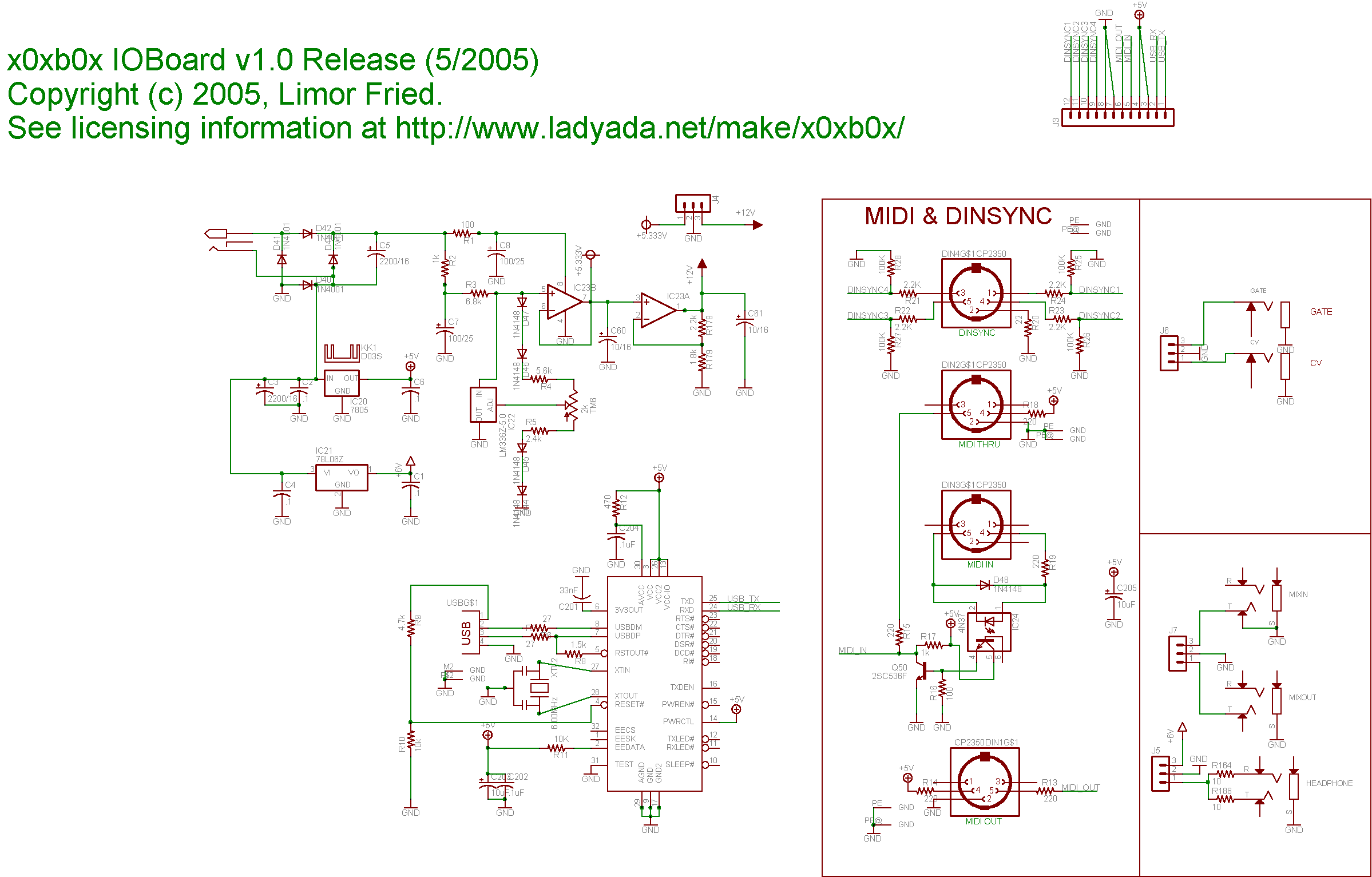