Back
[00:07:27] <tats> thanks Casper
[01:07:05] <pseydtonne> Hello. What's going on?
[01:08:29] <Casper> the energizer bunny. he's still going on and on and on
[01:09:53] <pseydtonne> Too bad that bunny isn't still getting work.
[01:10:06] <pseydtonne> Even the Petco puppet got a second round.
[01:10:18] <Thrashbarg> it's the Duracell bunny outside the US ...
[01:10:57] <pseydtonne> It can't be. That's a rival copany!
[01:11:02] <pseydtonne> Company, even
[01:11:14] <Thrashbarg> pseydtonne: but it is :P
[01:11:34] <pseydtonne> Okaydoke, then.
[01:31:03] <shibathedestroye> Hi. Not sure if this is the right place to ask this, but anyway... I've been playing around with an atmega328p, and I tried to disable the CKDIV8 fuse to make the device run at 8mhz. I did this, and the device is in fact running at 8mhz, but won't respond to SPI programming commands from avrdude anymore. The reset pin still works, so I don't think I accidentally set the RSTDISBL fuse.
[01:32:25] <shibathedestroye> Has anyone experienced this microcontroller becomming unstable or unresponsive to programming commands while running at a higher clock speed? I'm running it on 5v, which the datasheet says should be enough for this speed.
[01:32:51] <shibathedestroye> I'm using the GPIO pins on a raspberry pi as my programmer
[01:33:07] <pseydtonne> It's the SMD or the PTH one?
[01:33:19] <shibathedestroye> DIP 28 package
[01:33:25] <pseydtonne> Groovy.
[01:34:12] <pseydtonne> Try putting it in an Arduino Uno and reloading the bootloader and flashing any program to it. Get it back to boring.
[01:34:30] <pseydtonne> It's not brilliant, but it'll get you back to work.
[01:35:23] <shibathedestroye> I'm actually not using the arduino system, but I'm going to pick up an uno to try doing that. I actually don't have one yet, I've just been using my pi to program the chips
[01:35:32] <Dagger> I'm not sure how he's going to flash the Arduino bootloader when he can't flash the chip
[01:36:01] <shibathedestroye> dagger: that's my thought as well. wouldn't I have to hook up to the arduino's ISP port, which is basically what I'm doing now?
[01:36:10] <shibathedestroye> unless uno's have some other magic on them
[01:36:27] <Dagger> pretty much, yeah
[01:38:09] <pseydtonne> I think you can do the bootloader from the Arduino as well.
[01:38:57] <pseydtonne> In the crappy Arduino IDE: Tools -> Burn Bootloader
[01:39:46] <shibathedestroye> I'll try that when I get an uno, but I fear that if it's using the SPI programming interface, the chip still won't respond
[01:40:52] <Dagger> http://arduino.cc/en/Tutorial/ArduinoToBreadboard it requires this setup, so it's using the normal ISP interface for the target chip
[01:41:30] <Dagger> but that may in fact work when this RPi SPI-based thing doesn't, I suppose
[01:41:36] <pseydtonne> Good thing is: you're only out $5.50 if you can't get it to respond anymore.
[01:42:27] <shibathedestroye> yeah, in fact that's one of the sites I used to get the GPIO on the pi working with it. I suspect the pi's 3.3v logic might be part of the problem. if I run it through the arduino, the 5v might work better
[01:42:44] <shibathedestroye> pseydtonne: $3.50 from tayda :D I've got a stack of them, so no worries
[01:43:07] <shibathedestroye> I just don't want to shy away from fuses forever, and also don't want to burn through the chips too fast
[01:43:50] <pseydtonne> Valid point
[01:44:19] <shibathedestroye> I think I should ge the uno, and then build a high voltage programmer to reset the fuses even if they get totally stuffed. it'll be good experience to build it
[01:55:09] <anton02> whats the purpose of suspension on toy rc cars
[02:03:07] <antto> wouldn't it be more or less the same purpose as in real cars? ;P~
[02:28:58] <anton02> antto: no, cause comfort isnt an issue
[02:57:53] <myself> anton02: to keep the tires in contact with the road. Look up the concept of "unsprung weight" and you should be on your way to understanding it.
[06:39:54] <hetii> Hi :)
[06:39:55] <hetii> Could someone check page 15 at this datasheet
http://www.farnell.com/datasheets/1813107.pdf
[06:40:02] <hetii> The GND from c_co1 and c_co2 is floating?
[06:55:26] <Thrashbarg> hetii: I imagine it'd be connected to the GND the rest of the circuit is connected to, just they omitted it
[06:58:17] <hetii> yep, looks like :)
[06:59:12] <Lambda_Aurigae> GND is GND..it's your 0V reference point.
[07:00:42] <Thrashbarg> yup
[07:02:42] <Lambda_Aurigae> dates back to the days of old with marconi wireless when they called it Earth.
[07:02:52] <Lambda_Aurigae> using the Earth itself as a GND reference level.
[07:03:00] <Thrashbarg> and the wired telegraph before it
[07:03:05] <Lambda_Aurigae> true.
[07:06:58] <Thrashbarg> I wouldn't be surprised if it goes back to static electricity in the 1700's
[07:13:17] <Lambda_Aurigae> Long-distance electromagnetic telegraph systems from 1820 onwards[citation needed] used two or more wires to carry the signal and return currents. It was then discovered, probably by the German scientist Carl August Steinheil in 1836�1837,[1] that the ground could be used as the return path to complete the circuit, making the return wire unnecessary.
[07:13:37] <Lambda_Aurigae> so, early 1800s is when it started I would bet.
[07:13:53] <Thrashbarg> ok nice
[07:14:04] <Lambda_Aurigae> stolen straight from wikipedia..hehe
[07:14:13] <Thrashbarg> "According to Wikipedia..."
[07:16:59] <Lambda_Aurigae> gotta love the fact that the trans-continental telegraph worked best when it was raining and had problems during drought.
[07:17:50] <Thrashbarg> yeah haha
[08:51:05] <Duality> how hard would it be to design a syncronized counter consisting of d-flipflops ?
[09:15:22] <megal0maniac> Duality: If you have a clock source, then easy ;)
[09:16:46] <megal0maniac> Tedious, but easy enough
[09:18:04] <Lambda_Aurigae> flipflops are the building blocks of life...at least digital life.
[09:18:32] <Duality> megal0maniac: the thing is the d flipflops are housed in a register and share a clokc
[09:18:35] <Duality> clock
[09:19:54] <Lambda_Aurigae> you really need JK flipflops.
[09:20:18] <Lambda_Aurigae> or just a whole big honkin bunch of 2 input nand gates!
[09:20:57] <megal0maniac> Oh whoops. I missed the part about them being D type
[09:24:57] <Duality> i had the idea that i might somehow turn it into binary counter
[09:25:33] <Duality> the thing is j-k flipflops are really expensive :(
[09:56:23] <balrog-k1n> is avr-gcc supposed to support the #pragmas and attributes supported by gcc?
[09:56:42] <balrog-k1n> it seems to ignore all the #pragmas I try but not give any errors or warnings
[10:09:26] <Lambda_Aurigae> I've heard of people using #pragma in avr-gcc.
[10:52:44] <wondiws> hi, I'm getting different device signatures each time I try to download, what does this mean?
[11:11:25] <learath> wondiws: that something is broken
[11:11:34] <learath> what are you using to program
[11:11:37] <wondiws> avrdude
[11:13:51] <learath> how are you connected to your device
[11:14:14] <wondiws> myAVR dongle
[11:14:31] <wondiws> but I will try now to put this mega8 on my arduino board
[11:14:37] <wondiws> maybe that's better than this breadboard
[11:15:10] <learath> is the pinout safe?
[11:15:22] <wondiws> what safe?
[11:15:31] <learath> the arduino expects a 328p
[11:15:48] <wondiws> I will not break the arduino board, right?
[11:15:59] <wondiws> I have one arduino board that has an actual socket
[11:16:03] <learath> I don't know. what's the pinout
[11:16:10] <wondiws> but i have 5 of these atmega8's
[11:16:19] <wondiws> so if I break one, rather not, but not the end of the world
[11:16:37] <learath> I'd check the pinout
[11:17:09] <wondiws> VCC, GND, XTAL1, XTAL2 match
[11:17:17] <wondiws> that far I've just checked last second
[11:17:18] <learath> and the isp pins?
[11:17:54] <wondiws> yah, as well
[11:18:40] <wondiws> i still find it difficult to safely remove a tightly placed chip from DIP socket...
[11:19:03] <learath> there are tools to do that
[11:19:16] <wondiws> still it is :p
[11:19:51] <wondiws> but even if you have the best tools, I suppose there is a finite number of times you can place/replace a DIP chip?
[11:19:59] <Tom_itx> use vise grips to remove it
[11:20:04] <Tom_itx> or a crowbar
[11:20:24] <antto> stop. It's Hammer time!
[11:20:33] <Tom_itx> no
[11:20:38] <Tom_itx> that's the insertion tool
[11:21:02] <antto> i fix laptops with that ;P~
[11:32:57] <Jartza> hah
[11:32:58] <Jartza> https://www.dropbox.com/s/pxup1ox0gm2j83a/20140712_005.jpg
[11:33:42] <Jartza> I call that a success
[11:33:58] <Jartza> also the modem works, as you can see it has phone-plug-connector
[11:46:52] <wondiws> ok, in the Arduino Uno board the chip ATMega8 works
[11:47:14] <wondiws> My breadboard craftmanship wasn't any good apparantly
[12:03:23] <myself> wondiws: ZIF socket :p
[12:04:10] <atom1> if you screw it up you can always disolve the plastic cover and solder leads to the internal microleads
[12:05:30] <myself> bondwires
[12:30:01] <wondiws> myself, I don't think I can build an Arduino system on a single ZIF socket ;)
[12:38:59] <Jartza> next guest is to design a pcb that can actually be ordered from somewhere
[12:39:12] <Jartza> and not printed by myself :)
[12:58:39] <Jartza> that one is not yet ready for that
[14:13:48] <wondiws> ok, I tried writing the fuse bits, but mixed low and high up...
[14:14:04] <wondiws> how do I fix this? I can't simply rewrite...
[14:52:36] <Tom_itx> wondiws HVPP
[14:52:44] <Tom_itx> or figure out exactly what you botched up
[15:43:26] <Jartza> hmm. made the traces narrower, now the soldering was easier as the pads weren't that close to traces
[15:43:36] <Jartza> that one works too
[15:43:37] <Jartza> https://www.dropbox.com/s/jh1etnjjabzd5n7/20140712_008.jpg
[15:43:38] <Jartza> whee
[22:19:54] <randrews> Can someone look at my SD-card-reading code and tell me wtf I'm doing wrong?
https://gist.github.com/randrews/1d7f6bcdb63891b29fdb
[22:21:42] <randrews> I've been fighting this thing all day. I've tried using other SD libraries that other people made too, nothing works. But I'm pretty sure it's wired up correctly, because the SD slot is on the back on an LCD screen and the LCD screen part works (they share SPI wires, just have their own CS pins)
[22:33:53] <randrews> And the real screwy thing is that the CardInfo example sketch for the Arduino works.
[22:35:39] <randrews> I guess I can plug it into a scope and see exactly what the cardinfo sketch sends over, and then try to figure out wtf I went wrong.
[23:05:22] <Tom_itx> randrews i know there are 3 different init sequences depending what type of card it is
[23:06:39] <Tom_itx> scope or Logic Analizer would help probably
[23:10:04] <Tom_itx> randrews, what are you using for a buffer chip or are you using a resistor divider for the 3.3v SD?
[23:10:38] <randrews> There's a level shifter on the LCD, it uses that
[23:11:03] <Tom_itx> what level shifter?
[23:11:07] <randrews> I've been reading this:
http://elm-chan.org/docs/mmc/mmc_e.html and it looks like all the init sequences start with the idle command, so that should work no matter what
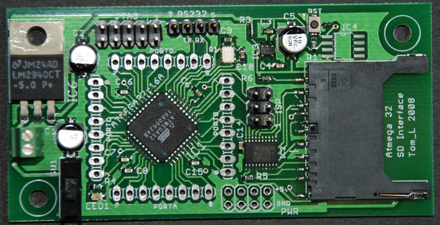
[23:11:07] <Tom_itx> http://tom-itx.no-ip.biz:81/~webpage/boards/atmega32_sd.jpg
[23:11:19] <Tom_itx> that was my attempt and you can see from the date it's been a while
[23:11:28] <Tom_itx> yeah i know about his code
[23:12:06] <Tom_itx> there are 3 different init sequenced depending if it's MMC, SD or SDHC
[23:12:40] <Tom_itx> MMC is the only non proprietary protocol
[23:13:04] <Tom_itx> otherwise the standard is hidden behind a $2k license
[23:13:34] <randrews> HC4050M is the only chip on there. It's one of these screens:
https://www.adafruit.com/products/1480
[23:13:50] <randrews> The Arduino sketch works with the exact same hardware se I'm pretty sure it's software
[23:13:57] <Tom_itx> yeah
[23:14:23] <Tom_itx> i'd get a logic analizer and capture the init from it and match it
[23:14:56] <Tom_itx> saleae.com is one i have
[23:15:07] <randrews> Unfortunately I wont have a bus pirate until Monday. :( If I haven't figured it out by then that's what I'll do
[23:15:10] <Tom_itx> it's got quite a few defined protocols to make it easier
[23:15:37] <Tom_itx> i think i narrowed my unsuccess to the buffer chip i used on it
[23:15:46] <Tom_itx> which was a maxim chip
[23:15:53] <Tom_itx> forget which one now...
[23:16:24] <Tom_itx> NXP makes a nice one and had i known about it back then i'd have used it instead
[23:17:32] <randrews> I wonder how much Arduino-specific stuff I'd need to pull out of their SD library in order to use it in my project?
[23:21:00] <Tom_itx> i wouldn't bother trying
[23:21:10] <Tom_itx> i'd try to capture the signal
[23:23:55] <Tom_itx> http://tom-itx.no-ip.biz:81/~webpage/pdf/mmc/
[23:24:06] <Tom_itx> there's all the info i've gathered on the subject
[23:28:14] <randrews> I think I'm going to try tho FatFs example code again, maybe I did something stupid last time.