Back
[04:13:06] <TheArtist> Hello again! Can somebody tell me if this ->
http://control7.net/blog/archives/21 is going to work for an attiny85?
[04:49:49] <Jartza> TheArtist: if you have arduino, this works:
http://www.rickety.us/2010/03/arduino-avr-high-voltage-serial-programmer/
[04:51:10] <Jartza> but if you do have arduino, I would make a "scratchmonkey" HVSP out of it
[04:51:14] <Jartza> or actually, I did
[04:51:15] <Jartza> http://microtherion.github.io/ScratchMonkey/
[04:51:32] <Jartza> that way I can flash attinys and have the reset pin used for other purposes
[04:52:10] <TheArtist> i dont have an arduino :(
[04:53:55] <Jartza> well, practically me neither, but I have atmega 328's
[04:54:28] <TheArtist> i have a hanging atmega328
[04:54:41] <TheArtist> but i dont know how to port the arduino code over
[04:55:52] <Jartza> well atmega328 is practically arduino
[04:56:40] <TheArtist> yep i know :P. But the code provided for most high voltage arduino programmers is for the arduino bootloader
[04:56:43] <Jartza> http://arduino.cc/en/Tutorial/ArduinoToBreadboard
[04:56:57] <Jartza> arduino bootloader can be flashed to 328
[04:57:57] <TheArtist> hmmm nice find
[04:59:56] <Jartza> or course that tutorial is using arduino to also flash the 328, but you can flash it whatever flasher you have :)
[05:00:15] <Jartza> http://arduino.cc/en/Main/Standalone
[05:00:23] <Jartza> that should also help
[05:01:03] <TheArtist> is there a map of the pins too? adruino<->atmega328
[05:01:29] <Jartza> although I'm using this $1 usb-rs232-serial-ttl converter, not the one used in that tutorial
[05:02:25] <Jartza> TheArtist:
http://www.hobbytronics.co.uk/arduino-atmega328-pinout
[05:04:08] <Jartza> I made 2 hvsp programmers out of my atmegas :)
[05:13:08] <Jartza> it's nice to have high voltage programmer especially with tinys
[05:13:28] <Jartza> you can use real slow speeds and the reset pin
[05:45:36] <mischief> man, i just can't get vusb to work
[05:49:00] <Lambda_Aurigae> mischief, not really surprising. It only works on some computers for me.
[05:54:50] <Lambda_Aurigae> mischief, are you running the chip at 3.3V or using the voltage limiting zener diodes?
[05:56:41] <Lambda_Aurigae> I find running the chip at 3.3V to be more stable than the version with the zeners.
[05:57:07] <Jartza> for me it worked the best with connecting 2 pieces of 1n4148 diodes to series and taking power through that :)
[05:58:08] <Lambda_Aurigae> Jartza, yeah,,that drops you down to within the 3.3V range.
[05:58:21] <Jartza> yep
[05:58:31] <Lambda_Aurigae> 1.4V drop
[05:58:36] <Jartza> I tried all kinds of zeners but somehow they didn't work
[05:58:46] <Jartza> 3.3v, 3.5v, 3.6v and 3.8v
[05:59:11] <Jartza> but now it seems to work nicely
[05:59:18] <Lambda_Aurigae> I've had mixed results with zeners...I think some of them don't recover fast enough.
[05:59:23] <Jartza> even with my android tablet
[05:59:47] <Jartza> well yeah, my zeners are some cheapest chinese ones I could find :)
[05:59:58] <Lambda_Aurigae> most of mine are too.
[06:00:38] <Jartza> but I had plenty of 1n4148s around, those worked nicely
[06:01:58] <Lambda_Aurigae> I've switched from vUSB to using icky PIC microcontrollers for USB interface.
[06:06:12] <mischief> Lambda_Aurigae: yes, i'm using 3.6v zener diodes
[06:06:23] <mischief> i seem to actually be having trouble programming the avr at all
[06:06:34] <mischief> avrdude says it was programmed but i don't see my led change
[06:06:54] <Lambda_Aurigae> can you get a verify?
[06:07:07] <Lambda_Aurigae> and, are you erasing the chip as part of the programming?
[06:08:55] <mischief> hm
[06:09:12] <Lambda_Aurigae> -e in the avrdude command.
[06:09:42] <mischief> avrdude: verifying ...
[06:09:42] <mischief> avrdude: 1032 bytes of flash verified
[06:10:11] <Lambda_Aurigae> that seems kinda small for a vUSB application.
[06:10:55] <Jartza> I switched from USB to modem ;)
[06:10:59] <mischief> i took vusb out to try to use the stupid led
[06:11:05] <mischief> but it wont blink :s
[06:11:19] <Lambda_Aurigae> then you likely have some hardware issue.
[06:11:21] <Jartza> 1032 sounds huge for stupid led
[06:12:34] <mischief> avrdude says the upload is all ok
[06:12:37] <mischief> ...
[06:12:45] <mischief> i'm using an avrisp2 and the led is green too
[06:13:05] <Lambda_Aurigae> aaand, your reset pin? is it floating or pulled high?
[06:13:37] <mischief> it's connected to the isp header
[06:13:53] <Lambda_Aurigae> when not connected to the isp, is it floating?
[06:23:19] <mischief> Lambda_Aurigae: it appears no
[06:24:14] <Lambda_Aurigae> it should be pulled high with a pullup resistor when not actively used for programming.
[06:29:34] <mischief> why wont it work ;_;
[06:30:08] <Lambda_Aurigae> without knowing your hardware setup, no clue.
[06:31:50] <Lambda_Aurigae> put the chip on a breadboard with nothing but an LED and pullup resistor for the reset.
[06:32:48] <mischief> is 10k ok
[06:32:53] <Lambda_Aurigae> yup.
[06:33:02] <mischief> can i have the programmer and the pullup at the same time?
[06:33:13] <Lambda_Aurigae> yes.
[06:33:27] <Lambda_Aurigae> do you have a crystal on the chip?
[06:33:41] <Lambda_Aurigae> and are the fuses set to run on the crystal?
[06:34:57] <mischief> well, that's what i've been fiddling with
[06:35:04] <Lambda_Aurigae> oh man...the "special effects" on Dr. Strangelove really suck....but, for a movie from 19
[06:35:10] <Lambda_Aurigae> 64,,it's ok.
[06:35:15] <mischief> i'm pretty sure it's supposed to be FF
[06:35:32] <mischief> there's a 16 mhz crystal attached
[06:35:45] <Lambda_Aurigae> what chip?
[06:35:51] <mischief> atmega328p
[06:36:16] <mischief> the led-blinking seems to work.. i just couldn't see it before lol
[06:36:24] <Lambda_Aurigae> ok.
[06:37:37] <Lambda_Aurigae> and what are your three fuses?
[06:39:48] <mischief> avrdude: safemode: Fuses OK (E:05, H:DA, L:FF)
[07:04:28] <mischief> tried everything i can think to do
[07:04:39] <mischief> time to take a break i suppose
[07:28:31] <Lambda_Aurigae> mischief, you are set for the wrong crystal.
[07:28:49] <Lambda_Aurigae> you have it set for external low frequency crystal.
[07:29:22] <Lambda_Aurigae> try 37 DA FF
[07:59:24] <mischief> .-.
[07:59:30] <mischief> i can't talk to the avr any more
[08:00:19] <mischief> ok, fixed
[08:00:22] <mischief> Lambda_Aurigae: that doesn't work
[08:00:40] <mischief> why set efuse to 37?
[08:01:21] <Lambda_Aurigae> hmmm...let me recheck...I think they are backwards
[08:03:00] <Lambda_Aurigae> you listed them backwards and I put them in the calculator wrong.
[08:03:02] <Lambda_Aurigae> however,
[08:03:04] <mischief> i was using
http://eleccelerator.com/fusecalc/fusecalc.php?chip=atmega328p
[08:03:08] <Lambda_Aurigae> are you using a bootloader?
[08:03:33] <mischief> uh, i think so
[08:03:37] <Lambda_Aurigae> think so?
[08:03:45] <Lambda_Aurigae> either you are or you aren't..
[08:03:53] <Lambda_Aurigae> do you have a bootloader installed?
[08:03:53] <mischief> i'm using makefiles that build with arduino libraries
[08:04:10] <mischief> yes?
[08:04:27] <Lambda_Aurigae> no clue. ardweeny libraries are fucked up.
[08:04:59] <Lambda_Aurigae> but arduino libs do not necessarily mean a bootloader.
[08:05:28] <Lambda_Aurigae> the bootloader on the arduino is used to get the program onto the device and is loaded separately.
[08:05:41] <Lambda_Aurigae> so, I would guess you do not have a bootloader.
[08:05:46] <Lambda_Aurigae> so turn off the boot reset vector.
[08:05:49] <Lambda_Aurigae> that will cause you issues.
[08:05:59] <Lambda_Aurigae> that is only useful if you actually have a bootloader onboard.
[08:06:26] <Lambda_Aurigae> and if you use avrdude with the -e to load your program then any bootloader on there would have been erased.
[08:06:52] <mischief> ok
[08:08:20] <Lambda_Aurigae> so, Low=FF High=DB Extended=FD
[08:25:54] <mischief> still no dice.
[08:26:07] <mischief> the linux computer says connect-debounce failed port 1 disabled
[08:26:22] <mischief> (on the vusb connection)
[08:40:25] <mischief> i give up for now
[08:40:29] <mischief> thanks for the help Lambda_Aurigae
[08:56:06] <mischief> oh!
[08:56:20] <mischief> i downloaded the source from github.. it works
[09:09:17] <mischief> \o/
[09:09:55] <mischief> so the fuses that work currently are 0xDF for low and 0xDE for high
[09:19:56] <_abc_> Hi. What do people prefer for simulation of avr micros? The supplied avr-insight and simavr?
[09:20:13] <_abc_> There is very little documentation for either. I hope to be corrected...
[09:48:24] <_abc_> Also it appears that running avr-insight.exe in wine under linux is a very bad idea. Lots of trouble, can't start gdb etc
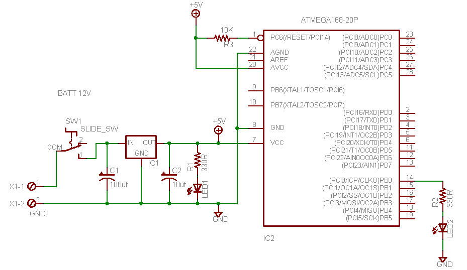
[10:57:30] <Tachyon`> do I strictly need the cap on the avr reset circuit or is the pullup resistor sufficient
[10:58:23] <Tom_itx> pullup is ok
[11:00:22] <Tom_itx> http://tom-itx.no-ip.biz:81/~webpage/how_to/atmega168/mega168_led_sch.png
[11:01:09] <Tachyon`> ah, thanks
[11:33:17] <_abc_> What is the correct bfd target name for building insight for avr target? avr-none-elf32?
[11:33:44] <_abc_> Please? It should be the same bfd target as a build for gcc toolchain
[11:33:53] <_abc_> Anyone?
[11:37:53] <Lambda_Aurigae> _abc_, I would guess nobody here active at the moment even uses insight.
[11:37:59] <Lambda_Aurigae> I know I've never bothered with it.
[11:40:07] <Tom_itx> or likely ever will
[11:40:39] <_abc_> insight is okay, but things like bfd names SHOULD be documented
[11:40:53] <_abc_> avr-insight.exe is distributed with the official avr tools for windows from atmel
[11:41:00] <_abc_> I am trying to build from source on linux
[11:42:02] <_abc_> Which I finally managed but am not sure about the bfd target name and I keep getting errors like 'blahblahpath.elf: cannot execute binary file'
[11:42:05] <_abc_> from insight
[11:43:07] <_abc_> my toolchain claims to have been configured with '--host=i686-pc-linux-gnu --target=avr'
[11:43:25] <_abc_> i.e. non standard bfd target name avr vs avr-none-elf32
[11:43:38] <_abc_> where the latter is the canonical (required?!) bfd name
[11:53:48] <_abc_> Wonderful. insight 6.8.1 compiled fresh does not talk to avr-gdb which is older. Protocol errors.
[11:53:51] <_abc_> BAH
[12:02:13] <Tom_itx> why would they change the protocol?
[12:04:50] <_abc_> Because the old gdb I have is fricking ancient and probably speaks Ancient Greek? Circa 2005?!
[12:04:54] <_abc_> Another:
[12:05:33] <_abc_> simulating in text mode with atmel avr-gdb on an elf file known to work fine in harware, target it atmeg168:
[12:06:32] <_abc_> avr-gdb commands are: avr-gdb ; target sim ; load theelf.elf ; break somewhere_relevant; run -- the somewhere_relevant addresses a wdt_reset(); which comes from avr/watchdog.h and is standard
[12:06:39] <_abc_> When I step on that I get:
[12:06:40] <_abc_> 1394 wdt_reset();
[12:06:40] <_abc_> (gdb)
[12:06:40] <_abc_> Unhandled instruction at pc=0x6e0, op=95a8
[12:06:40] <_abc_> Bad instruction at pc=0x6e0
[12:06:55] <_abc_> Is avr-gdb somewhat lacking in brains?
[12:07:09] <_abc_> Can you tell if that is an illegal opcode? I can't.
[12:14:54] <_abc_> https://sourceware.org/binutils/docs/as/AVR-Opcodes.html says 0x95A1 is break What the frick
[12:16:01] <_abc_> Watchdog reset should be 1001010110101000 which is 0x95A8
[12:16:15] <_abc_> Is avr-gdb sometimes confused?
[12:18:01] <RikusW> quite possible
[12:19:35] <_abc_> Sigh
[12:20:05] <_abc_> disasm shows nops at that address. 0x6e0 is interpreted as 080006e0 and I can't force it down to 000006e0
[12:20:09] <_abc_> what is going on?!
[12:21:16] <_abc_> ARGH it was a macro
[12:21:30] <_abc_> Okay the real code disassembles correctly and there is a wdr there as expected
[12:21:33] <_abc_> not a break
[12:21:53] <_abc_> code is literally:
[12:21:54] <_abc_> 0x000006de <+248>: nop
[12:21:54] <_abc_> 0x000006e0 <+250>: wdr
[12:21:54] <_abc_> => 0x000006e2 <+252>: ret
[12:22:12] <_abc_> this causes avr-gdb to bomb out
[12:22:16] <_abc_> as above
[12:22:27] <_abc_> can you please say what avr-gdb version are running on linux?
[12:27:32] <_abc_> Unhandled instruction at pc=0x6e6, op=95a8
[12:27:32] <_abc_> Bad instruction at pc=0x6e6
[12:27:46] <_abc_> ^ again, this time I inserted a lot of nops before and after, there is no room for error
[12:28:23] <_abc_> Can anyone please compile or just pull a simple program and see if their avr-gdb chokes on wdt_reset() please?
[12:29:35] <_abc_> Simply load an existing elf in avr-gdb command line mode, using: file thefile.elf; target sim; load; break thefilewithwdtreset:lineat run
[12:29:50] <_abc_> I am curious if just my version is cursed or if others are also cursed.
[12:31:21] <_abc_> avr-gdb --version
[12:31:22] <_abc_> GNU gdb (GDB) 7.2
[12:31:29] <_abc_> ^ please say yours?
[12:33:39] <Lambda_Aurigae> 7.5 here
[12:33:42] <Lambda_Aurigae> but never used it.
[12:33:45] <Lambda_Aurigae> don't even know how.
[12:33:48] <_abc_> hah
[12:34:03] <Lambda_Aurigae> it's the default for ubuntu.
[12:34:37] <_abc_> http://cs.baylor.edu/~donahoo/tools/gdb/tutorial.html 5 minute tute
[12:35:07] <_abc_> note for sanity type out commands like b (type break or press tab for auto completion).
[12:35:08] <Lambda_Aurigae> I have no use for it really.
[12:35:50] <_abc_> right
[12:37:01] <mischief> omg
[12:37:04] <mischief> vusb is a constant fight
[12:37:06] <Lambda_Aurigae> and have never used this machine for avr development. just installed the stuff in case I need to.
[12:37:18] <Lambda_Aurigae> my avr work is done on the machine in the workshop.
[12:39:00] <_abc_> Lambda_Aurigae: ...
[12:49:56] <_abc_> Okay I confirm that the built-in sim in avr-gdb is a joke and does not sim key hardware features such as interrupts, watchdog and worse.
[12:50:03] <_abc_> So just write it off as a sim.
[12:50:33] <_abc_> This is the official avr-gdb in the official linux code download from atmel.
[12:52:51] <_abc_> hah Lambda_Aurigae you a Halo player? ;)
[13:00:05] <emma> I wish I had the skills you guys have here.
[13:12:46] <_abc_> Nobody was born omniscient, or with my current headache
[13:12:53] <_abc_> @ emma
[13:13:11] <_abc_> (headache caused by 'open sores' software)
[13:14:11] <learath> clearly you've never called Microsoft "Technical" "Support" :P
[13:14:28] <learath> People whine about "open sores" have *NO IDEA* how bad closed source software is.
[13:15:19] <_abc_> Oh I have. A few times, when I was a paying beta tester. I got over that long time ago.
[13:16:13] <_abc_> In a nutshell, my message to open sores code is: DOCUMENT thy code and changes. Even if it's just a reply to some message on a forum 2 years after the fact.
[13:17:48] <_abc_> I have been using open source code and linux in particular, and authored some, since about 1996, continuously.
[13:22:08] <rue_more> http://www.ebay.ca/itm/6-Color-Mini-Solderless-Prototype-Breadboard-Bread-Board-for-Arduino-Shield-/390681168488
[13:22:09] <rue_more> hahaha
[13:23:20] <rue_more> http://www.ebay.ca/itm/PRO-MINI-ATMEGA328-5V-16M-MWC-avr328P-Development-Board-for-Arduino-XTW5-/121363416834
[13:23:30] <rue_more> I'd pay that just for the chip...
[13:27:48] <ColdKeyboard> Is my LogicSniffer bugged or am I reading something wrong... I have 50% duty cycle and my cursors say that B-A is 10uS. However, frequency is 95kHz... ? :S
[13:29:14] <rue_more> zippo:~/alarms# units 1/100000hz us
[13:29:15] <rue_more> * 10
[13:29:15] <rue_more> / 0.1
[13:30:08] <rue_more> nudge the cursor :)
[13:30:44] <ColdKeyboard> Could be the resolution or something... Or it should say 10.5uS :)
[13:31:08] <ColdKeyboard> I just noticed it so I wanted to see if anyone else had a similair "issue" :)
[13:32:51] <rue_more> what is a good price on a m32 dip now?
[13:33:02] <rue_more> about $6 yea?
[13:42:29] <RikusW> get m32a it should be cheaper
[13:44:28] <learath> m32a?
[13:49:47] <RikusW> atmega32a
[13:50:12] <RikusW> m32a is avrdude shorthand
[13:50:38] <learath> ah
[13:50:47] <learath> meh, it's not an expensive chip
[13:50:51] <learath> unless you are using hundreds
[13:51:41] <_abc_> redux: insight-6.8.1 does not work with simulavr but avr-gdb works
[13:51:43] <Tom_itx> even cheaper by the hundreds
[13:52:17] <_abc_> problem is protocol errors in insight->simulavr comms (which do not exist in avr-gdb talking to simulavr)
[13:53:29] <_abc_> Anyway I gtg
[14:45:03] <Lambda_Aurigae> _abc__, I thought it was a movie.
[14:45:08] <Lambda_Aurigae> how can you play a movie?
[14:46:58] <_abc__> What?
[14:47:09] <_abc__> Halo is a game.
[14:47:34] <Kev> it's both
[14:47:59] <_abc__> Also the distinction between games and movies is blurring fast
[14:48:14] <Lambda_Aurigae> only video games I play are kerbal and minecraft...plus some x-plane flight sim.
[14:48:37] <_abc__> Also, to play a movie, press 'play'...
[14:59:47] <malinus> _abc__, already more gameplay than some "games"
[15:11:39] <RikusW> _abc__: In the old video games you also had to press "play" ;)
[15:55:22] <mischief> oh man
[15:55:35] <mischief> vusb is so slow in conjunction with this avr
[15:57:21] <bitd> I need some help wrapping my head around this.
[15:57:24] <_abc__> You made vsusb work? It never worked for me
[15:57:29] <bitd> I have a problem with my crystal.
[15:57:43] <bitd> It seems to pickup a lot of noise, and makes the crystal work erratic.
[15:58:00] <bitd> Would tying my crystal case to ground help?
[15:58:08] <bitd> Reading a lot of different opinions on this.
[16:06:08] <_abc__> Using proper load caps helps
[16:06:21] <_abc__> What xtal? 16MHz?
[16:08:19] <bitd> Yes, 16MHz.
[16:08:46] <bitd> Used all the recommended caps.
[16:08:51] <bitd> All the same issue.
[16:10:35] <_abc__> 2x22pF or so? Change xtal and use 100nf decouplung directly at mcu power pins. Should work nicely.
[16:11:24] <bitd> Change xtal? why so?
[16:15:38] <_abc__> Some are duds.
[16:18:17] <Lambda_Aurigae> bitd, doing it on solderless breadboard?
[16:18:58] <bitd> Nope, soldered on a pcb.
[16:19:56] <Lambda_Aurigae> sounds like you have either a bad crystal or noise somewhere on the board.
[16:20:08] <bitd> Well, the fact is.
[16:20:10] <Lambda_Aurigae> can't say as I've ever had a bad crystal before.
[16:20:23] <bitd> If I remove the crystal and make it run on the internal osc, it works fine.
[16:20:39] <bitd> If it works on the crystal it sometimes "stops" and resumes shortly after.
[16:20:55] <Lambda_Aurigae> again, bad crystal or some noise on the board.
[16:21:18] <bitd> Switched two crystals already :)
[16:21:31] <bitd> So noise it is.
[16:22:00] <bitd> Even a normal arduino will fault when close to the ignition coil.
[16:22:09] <Lambda_Aurigae> umm.
[16:22:16] <Lambda_Aurigae> you are doing this near an ignition coil?
[16:22:26] <bitd> I am driving an ignition coil.
[16:22:58] <Lambda_Aurigae> that could majorly affect it, yes.
[16:23:04] <bitd> :-)
[16:23:34] <bitd> Got it working fine without a crystal.
[16:23:53] <bitd> But I would like to find out how to run it with.
[16:24:00] <Lambda_Aurigae> shielding and isolation.
[16:24:02] <bitd> Learning project mostly.
[16:24:11] <Lambda_Aurigae> optoisolators and EMF shields.
[16:25:06] <bitd> Already using optoisolator to drive the tip.
[16:25:13] <bitd> Which drives the power transitor.
[16:25:16] <bitd> Which drives the coil.
[16:25:37] <Lambda_Aurigae> no common ground and physical EMF shielding around the circuit?
[16:26:25] <bitd> No physical shielding around the circuit.
[16:27:14] <Lambda_Aurigae> crystal oscillator is rather picky about EMF flying around.
[16:27:20] <bitd> I see.
[16:27:28] <Lambda_Aurigae> RC oscillator, which is what is the internal oscillator, isn't nearly so picky.
[16:28:37] <bitd> Can I use a ceramic oscillator at that same speed?
[16:29:08] <Lambda_Aurigae> I've seen them at 12MHz with ceramic oscillator.
[16:30:03] <bitd> Are ceramic oscillators less susceptible to EMF?
[16:30:53] <Lambda_Aurigae> on that one I'm not sure. I would say as a gues, somewhat less but more so than the built in RC oscillator.
[16:31:03] <Lambda_Aurigae> also, how close to the AVR is your crystal?
[16:31:27] <Lambda_Aurigae> circuit length between AVR and crystal and to the caps is a major issue.
[16:32:13] <bitd> Yeah read that memo after I printed the board.
[16:32:47] <bitd> Crystal is right at the mcu, the caps are not. About an 0.75 inch between caps and crystal
[16:32:55] <Lambda_Aurigae> and the longer they are the more they are prone to interference....the longer the antenna and all that.
[16:34:31] <bitd> http://www.atmel.com/Images/doc8128.pdf
[16:34:36] <bitd> That explains it quite nicely.
[16:49:16] <mischief> how the heck do i make a usb keyboard repeat keys
[17:11:04] <Lambda_Aurigae> mischief, send the keycode repetedly.
[17:36:45] <Jartza> hmmh
[18:02:12] <Jartza> I guess my analog part of the modem behaves now as I like it to
[18:24:39] <Jartza> https://www.dropbox.com/s/1ldgo02ly08toub/Screenshot%202014-06-16%2002.06.17.png
[18:24:54] <Jartza> someone could tell me why this is so wrong :)
[18:24:56] <Jartza> (or is it?)
[18:25:20] <Jartza> the audio in comes from headphone-connector and I'm only interested on the rising edges of the signal
[18:27:58] <N1njAway> Jartza: D1 will clamp the signal to a maximum as per the forward voltage of the diode. The rest just acts as a biased high-pass filter. You can always add another D1 but reverse-biased AFTER C1 to dc-shift the level up higher, but it may not be necessary.
[18:29:31] <Jartza> yes, D1 was added because I'm running the attiny at 3.3V
[18:29:52] <Jartza> and without it the high peaks sometimes went to 4.5V
[18:30:10] <Jartza> which according to datasheet is over max. (VCC + 0.5V)
[18:30:24] <Jartza> also the signal sometimes went to -700mV
[18:30:38] <Jartza> adding the D1 also seemed to address that (I don't know why) :)
[18:31:06] <Jartza> and actually I did have 10k on both the R1 and R2
[18:31:22] <Jartza> but as I told, I'm not really trying to sample "audio" as such, I'm interested on the rising edges
[18:32:12] <Jartza> and the signal is quite "wobbly" at the bottom, because I'm more or less sending 48kHz 8 bit sampled data with only values "255" or "0" :)
[18:32:45] <Jartza> I guess the audio dacs don't do so well in cheap devices... so I biased the signal a bit lower, so I only get the "peaks" of the signal
[18:32:58] <Jartza> working quite well, and looking quite nice
[18:34:08] <Jartza> https://www.dropbox.com/s/wnjn0abrq44t7nx/IMG_20140614_202736.jpg
[18:34:31] <Jartza> the peaks are a bit "cut off"
[18:34:46] <Jartza> it doesn't matter in my use
[18:35:00] <Jartza> the cursor is at 1.65V
[18:35:34] <Jartza> which I believe is quite close the the "trigger" value of INT0 if running at 3.3V (shouldn't it be 50% of VCC?)
[18:37:01] <Jartza> I still do get some occasional negative spikes, but not more than -60mV
[18:37:14] <Jartza> but rarely... and that fits to specs
[18:38:02] <Jartza> and by biasing a bit "lower", I actually get the modem working nicely with quite low volume
[18:38:37] <Jartza> even
https://www.dropbox.com/s/za2og29h4hirvuq/IMG_20140615_224738.jpg
[18:38:49] <Jartza> even with that I got intact data :)
[18:39:36] <N1njAway> Very nice!
[18:39:39] <Jartza> barely crossing the 1.65V and 340mV peak to peak :)
[18:39:44] <Jartza> (btw. I love scoping)
[18:39:47] <Jartza> :D
[18:39:58] <Jartza> oh yeah... and did I mention, 12kbps
[18:40:22] <Jartza> shenanigans:firmware jartza$ avr-size --format=avr --mcu=attiny85 modem.o
[18:40:26] <Jartza> Program: 262 bytes (3.2% Full)
[18:43:05] <Jartza> https://www.dropbox.com/s/uxjgzmfxp38u142/IMG_20140614_194506.jpg
[18:43:14] <Jartza> that's played from my mac with maximum volume
[18:43:55] <Jartza> the C2 is there because for example nexus 4 and jolla both got a strange ripple even when not playing anything, but only if they are connected to charger
[18:44:23] <Jartza> and that ripple sometimes went over the 1.65V as the bias is bit below the trigger level
[18:45:03] <Jartza> but... as being new to making my own electronics, just wanted to ask someone elses opinion, that am I doing something really wrong here? :)
[18:45:48] <Jartza> and I guess it's more user friendly when I can just say "pump the volume to the max" :)
[18:46:21] <Jartza> nexus 4 gives maximum 1.0V pk-pk, Jolla gives 1.24V pk-pk, iPad mini 1.4V pk-p
[18:46:51] <N1njAway> Jartza: As long as it works that's really what's important.
[18:48:50] <N1njAway> Only other thing you may want to add is to try putting something like a 1K or 10K on the input pin itself, and possibly adding a negative-going clamping diode so you aren't ever underrunning the signal in to the Atmel. Though if you add the 1-10K on the input pin, that will help protect from ever having enough current flow to the Atmel to damage it. The Atmel SHOULD have internal clamping diodes
[18:48:50] <N1njAway> on the pins that help mitigate these over/underruns, but only if they are current-limited excursions.
[18:48:58] <N1njAway> That's the only thing that occurs to be readily.
[18:49:04] <N1njAway> Other than that, if it works, it works. :D
[18:49:34] <N1njAway> Glad to see it's doing well and you are enjoying the scope. Be back later!
[18:49:39] <Jartza> well it works :)
[18:49:47] <Jartza> and I got rid of the too high & too low voltage
[18:50:21] <Jartza> and actually got speed improvements and more reliability
[18:50:32] <Jartza> as I only need those peaks to barely go over the trigger voltage
[18:52:15] <Jartza> as I also got permission to release the source code at some point, I'd like to make it work for others too ;)
[19:08:46] <Jartza> oh... works even with 260mV pk-pk
[19:36:39] <Jartza> oh well.... nighty night :)
[20:36:44] <ColdKeyboard> Can someone suggest IR proximity sensor circuit? I made one using IR diode and IR phototransistor. I fed 40KHz to the LED and used photo transistor to get the IR light, amplify it with NPN transistor and then feed it to another transistor that has 40KHz high-pass filter on base input but I didn't get very satisfying results...
[20:38:11] <ColdKeyboard> It worked when LED and Phototransistor were in direct line of sight of one another, but I would like to place them side by side and detect when I put hand, paper etc. on top of them (possibly it will have glass between the circuit and the object).
[20:38:29] <timemage> ColdKeyboard, hmm, you could try using a remote control receiver rather than a phototransistor.
[20:38:50] <timemage> ColdKeyboard, oh, nevermind.
[20:39:08] <timemage> ColdKeyboard, i thought you were using this like a large photo interrupter.
[20:40:57] <ColdKeyboard> Well I would like to be able to detect if some object is placed on top of the glass table or something like that... This circuit that I have "works ok" but not like I inteded it to work :)
[20:41:43] <ColdKeyboard> I'm not sure if I should go for Op-Amp or maybe do some ADC or something else... the simpler the solution the better :)
[20:42:13] <Casper> ColdKeyboard: why pulse it?
[20:42:37] <timemage> ColdKeyboard, well, the reason i was thinking ir receiver was just that they're built with a bandpass filter. but they also have other features that would ruin it for your application. anyway, i was wondering what would happen if you switched the filter.
[20:42:46] <ColdKeyboard> So that IR from incadesent (I hope that's the right word) doesn't turn the sensor on.
[20:43:23] <ColdKeyboard> or so that lights on/off doesn't affect sensor.
[20:43:41] <ColdKeyboard> timemage: What do you mean by switching the filter?
[20:44:05] <timemage> ColdKeyboard, using bandpass rather than highpass.
[20:45:54] <ColdKeyboard> Well I don't think there is higher IR light than 40KHz present in my enviroment and I was afraid using another set of RC filter would further attenuate the signla...
[20:46:37] <ColdKeyboard> You think bandpass would make much diference?
[20:47:24] <Casper> ColdKeyboard: light WILL affect even 40kHz
[20:47:31] <ColdKeyboard> The circuit works but the problem is it works when they are in direct line of sight, if I set reciever and transmitter side-by-side and place a mug, paper, hand on top of them (let's say 0.5-5cm), nothing happens...
[20:47:39] <Casper> it add an offset to everything
[20:49:38] <ColdKeyboard> Ok, so I should make bandpass like 35-45KHz?
[20:50:23] <ColdKeyboard> Any other ideas how to improve the detection? I don't understand why it doesn't detect reflected light from my hadn, mug, paper or any other object placed directrly above
[20:51:14] <Casper> first, you don't see IR
[20:51:25] <Casper> so you don't know how stuff reflect
[20:51:48] <Casper> so a white sheet of paper may actually absorb IR
[20:52:17] <Casper> but then, if you use some modules, it will decode only valid signal
[20:52:34] <Casper> so you may be using the wrong thing, literally
[20:53:14] <Casper> https://www.flickr.com/photos/93694432@N04/12583714024/ <=== ex of what I mean for IR stuff
[20:53:26] <Casper> left is standard, right is IR only, from IR leds
[20:53:34] <Casper> notice the black that is white
[20:55:34] <Casper> so you may want to have a filter that detect the IR level when off, then another when on, then compare for a certain difference
[20:56:23] <ColdKeyboard> So maybe turning IR on, reading ADC on phototransistor, turning IR off and then read ADC again and compare them?
[20:56:35] <Casper> that may be a way
[20:56:56] <Casper> I do not know if there is another easier way... surelly, but I am unsure
[20:57:38] <ColdKeyboard> Well, I don't mind this one if it's going to work alright. :)
[21:51:34] <umquant> is it pretty standard when organizing source code to have a directory within lib for each "module"?
[21:52:34] <umquant> For example: lib/spi - lib/usart - lib/enc28j60
[21:52:55] <umquant> then within each one of those directories I have a .c and .h file for that module