Back
[01:42:36] <rue_shop2> that makes sense, it looked like microchip was trying to make sure people had to buy official programmers from them
[01:44:27] <rue_shop2> are they charging more than $100 for that programmer?
[01:45:14] <rue_shop2> I see $50
[01:46:02] <rue_shop2> sounds like there are others that run up to $200
[01:46:03] <rue_shop2> wow
[01:46:19] <rue_shop2> and you can get an avr programmer down around $20
[01:46:58] <rue_shop2> ;) I wonder if I should start making ATA programmers at about the $5 mark
[03:58:15] <megal0maniac> rue_shop2: It's a little bit of apples/oranges. All of pic's programmers also do debugging. The pickit2 is limited, but the pickit3 supports nearly everything while costing the same as the AVR dragon. There aren't any official $34 programmers (like avrispmkii) or ones that can be cloned for $20 (with the exception of the EoL pickit2) but on the other hand, the $50 pickit3 is comparable to the jtagice3
[03:58:35] <megal0maniac> Which sells for $99
[03:59:06] <megal0maniac> rue_shop2: Also, can you please make me a 12V UPS?
[04:02:08] <megal0maniac> Was thinking of taking a 12V transformer and lightening up on the filtering (maybe remove the zener, smaller cap) until I get a messy 13V to charge the battery, then filter after the battery and into my device
[04:03:03] <megal0maniac> Now I'm thinking I could use an attiny to monitor the battery voltage stuff
[04:12:36] <jacekowski> megal0maniac: battery will serve as quite good filter
[04:14:18] <megal0maniac> jacekowski: Fair point. Maybe just a zener and filter cap on the other end
[04:15:16] <megal0maniac> Am I right in assuming that "noisy" 13V is better for charging than the otherwise filtered output?
[04:18:12] <megal0maniac> Off to DHL. Brb
[08:17:09] <Duality> hi
[08:17:35] <Duality> I have got problems with my uart doing weird when I enable a timer interupt.
[08:18:08] <Duality> how could I debug what could be the cause?
[08:25:47] <sjokkis> Duality: could you explain the problem in more detail?
[08:43:10] <Duality> sjokkis: when i have a timer running on over flow interupt, it blocks my serial io, I want my serial io to have precedence over anything. when I make the timer ovf ISR_NOBLOCK the timer interupt doesn't work anymore
[08:47:25] <sjokkis> Duality: so the timer is using one of the uart pins?
[08:47:49] <Duality> sjokkis: no
[08:48:25] <sjokkis> Duality: so how is the uart acting weird?
[08:49:05] <Duality> sjokkis: the uart transmits either not or slow. and seems to be the same for recieving
[08:49:19] <sjokkis> how often does your timer trigger?
[08:49:31] <Duality> as many times as possible
[08:49:44] <sjokkis> approximately what frequency?
[08:51:05] <Duality> fcpu it uses no prescaler
[08:51:19] <sjokkis> okay. are you doing a lot of work in the timer interrupt?
[08:51:50] <Lambda_Aurigae> sounds to me like you need a second smaller chip to do your high speed timer stuff.
[08:52:11] <Lambda_Aurigae> that AVR is limited in how much it can do, specially if a timer is running full bore and doing stuff.
[08:52:14] <sjokkis> yeah, that's what i'm thinking
[08:52:26] <sjokkis> or maybe defer the work that's being done in the timer to main context
[08:53:23] <Lambda_Aurigae> multiple processors are often needed for realtime stuff like that.
[08:53:25] <Duality> sjokkis: as it is yes :) kinda
[08:53:52] <Lambda_Aurigae> copiers do just that...at least 5 different processors in one model of Xerox that I know of.
[08:54:11] <Duality> I currently use the timer to update a display
[08:54:16] <Lambda_Aurigae> and two of those are FPGAs
[08:54:46] <Lambda_Aurigae> Duality, I would add a second processor just for the display..
[08:56:44] <Duality> well the problem is that I can't I would love to, but can't
[08:57:03] <Lambda_Aurigae> then you need a faster processor.
[08:57:09] <Lambda_Aurigae> or cut your update speed down.
[09:02:27] <Duality> ok
[09:02:53] <Duality> 50Hz woul in theory be enough as the human eye can't see it updating at that speed anyway :)
[09:02:58] <Lambda_Aurigae> with that timer running full bore it is not leaving time for anything else.
[09:03:09] <Lambda_Aurigae> 30Hz is sufficient really.
[09:03:13] <anton02> how do you send AT commands to a serial device?
[09:03:25] <anton02> device in question's data sheet:
http://topelectronics.com.au/image-eb/mo/JY-MCU-HC-06%20BT_Module.pdf
[09:03:26] <Lambda_Aurigae> ATH)
[09:03:27] <Lambda_Aurigae> err
[09:03:29] <Lambda_Aurigae> ATH0
[09:03:32] <Lambda_Aurigae> ATH1
[09:03:52] <Lambda_Aurigae> those put modem on hook and take it off hook respectively.
[09:04:04] <anton02> port E is my serial device on my atmega64
[09:04:12] <Duality> connect said device to computer with a usbserial and send the commands
[09:04:24] <Lambda_Aurigae> I bet your serial device is on port E but port E is not all serial device.
[09:04:52] <anton02> PE0 to PE3
[09:05:11] <Lambda_Aurigae> AT commands are just a set of commands that start with AT which are used for controlling modems...they are plain ascii text.
[09:05:17] <anton02> pe2 and pe3 are output compare patch
[09:05:20] <anton02> match*
[09:05:56] <anton02> oh so just PE1 = "AT string"
[09:06:01] <Lambda_Aurigae> no.
[09:06:16] <Lambda_Aurigae> your question then should be, how to send data over USART from an avr.
[09:06:47] <Lambda_Aurigae> you will have to setup the USART and send data through that...there are many tutorials out there for that...let me google it for you.
[09:07:01] <anton02> ok thanks i just didnt know what to search for
[09:07:07] <Lambda_Aurigae> http://tom-itx.dyndns.org:81/~webpage/abcminiuser/articles/avr_usart_index.php
[09:07:52] <anton02> what does USART stand for?
[09:07:55] <Lambda_Aurigae> I would recommend reading the entire datasheet for your AVR before starting anything,,but I'm a bastard and require people to read things.
[09:08:13] <Lambda_Aurigae> http://www.google.com/url?sa=t&rct=j&q=&esrc=s&source=web&cd=1&cad=rja&uact=8&ved=0CCgQFjAA&url=http%3A%2F%2Fen.wikipedia.org%2Fwiki%2FUniversal_asynchronous_receiver%2Ftransmitter&ei=yM82U-rHFKaisQT-n4HIBQ&usg=AFQjCNG44bDomrsVgBHPKkcRmQwywWr9_w&bvm=bv.63808443,d.cWc
[09:08:23] <sjokkis> anton02:
https://www.google.com/search?q=usart
[09:08:25] <Lambda_Aurigae> http://en.wikipedia.org/wiki/Universal_asynchronous_receiver/transmitter
[09:08:33] <Thrashbarg> it'd be nice if Google didn't link to Google metalinks...
[09:08:39] <Lambda_Aurigae> yeah.
[09:08:45] <Lambda_Aurigae> I keep forgetting that Thrashbarg
[09:08:59] <Thrashbarg> I remember they stopped it ages ago then started again
[09:09:31] <Lambda_Aurigae> anyhow, that's UART which I posted...the AVR has a USART...which adds Synchronous in there.
[09:12:01] <Lambda_Aurigae> again, I would stress, READ the datasheet...
[09:12:55] <Lambda_Aurigae> just like my copier techs who are constantly calling me with questions and my first question to them is,,did you look at the manual? if they answer no then I make them go look it up for themselves and 9 times out of 10 it's right there.
[09:13:39] <Lambda_Aurigae> AVR datasheets are awesome...the best I've ever seen...and include code segments in both C and Assembly for most things.
[09:15:59] <Lambda_Aurigae> http://www.techlib.com/ hmmm..interesting site.
[09:17:17] <sjokkis> I agree completely, Lambda_Aurigae. Too bad the Xmega and SAM datasheets aren't nearly as good
[09:17:25] <Lambda_Aurigae> yeah.
[09:17:47] <Lambda_Aurigae> and PIC datasheets are amongst the lower grade too.
[09:18:21] <sjokkis> Yeah? Not familiar with those
[09:18:45] <Lambda_Aurigae> split out into multiple documents often times and not well written.
[09:18:49] <sjokkis> The AVR datasheets are probably made here in Norway, since AVR is made here. Maybe the other datasheets are written somewhere else
[09:18:52] <Lambda_Aurigae> specially for the pic32.
[09:26:30] <Duality> what is more power friendly a lower cpu freq or a higher for les time a lower clock could be on ?
[09:26:52] <Lambda_Aurigae> all depends on the processor
[09:28:43] <Casper> anton02: btw, the USART on the avr have several name, depending on which avr you use
[09:28:57] <Lambda_Aurigae> casa
[09:28:58] <Casper> it depend on the function that it support
[09:29:02] <Lambda_Aurigae> Casper, yeah...usart or
[09:29:05] <Lambda_Aurigae> u
[09:29:07] <Lambda_Aurigae> grrr
[09:29:08] <Lambda_Aurigae> usi
[09:29:13] <Lambda_Aurigae> usart or usi
[09:29:25] <Lambda_Aurigae> I much verily dislike this keyboard.
[09:29:41] <Lambda_Aurigae> enter key is too big and I keep hitting it when I want to backspace.
[09:29:57] <Casper> there is many flavor of serial port, ex: standard asynchronous, synchronous, spi, smbus, 1 wire and a few others
[09:30:19] <Casper> they are all a variant of it, with more or less wires and complexity
[09:32:14] <Casper> ex, the asynchronous do not have any clock info, both side must be setted to the same serial speed. The receiver must time the bits to be able to know what is the data..... synchronous uart have another wire for the clock, so it's not an issue (but add another wire)
[09:32:33] <Casper> but in both, the data use the same hardware
[09:38:40] <Lambda_Aurigae> methinks you scared him.
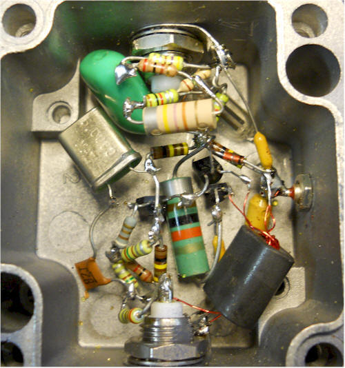
[09:39:40] <Lambda_Aurigae> http://www.techlib.com/electronics/graphics/VLFblo5.jpg now that's some skill!
[09:41:38] * megal0maniac_afk bookmarks as example of "deadbugging"
[09:41:51] <Lambda_Aurigae> http://www.techlib.com/electronics/VLFblockconv.htm
[09:41:55] <megal0maniac_afk> "Skill" is not the word I'd use :P
[09:41:58] <Lambda_Aurigae> schematic is on that page along with that.
[09:42:53] <Sevalecan> Duality \o/
[09:42:59] <Sevalecan> wait... wrong channel
[09:43:03] <Sevalecan> and wrong person
[09:43:05] <Sevalecan> \o/
[09:46:39] <megal0maniac> \o/
[09:47:01] <Kraln> hey guys, we developed a c unit testing framework for use with embedded; anyone want to have a look at let us know your thoughts?
[09:47:17] <Thrashbarg> Lambda_Aurigae: neat circuit, looks like a two quadrant multiplier or VCA... I'd be curious to see if there are a crapload of harmonics or not though
[09:50:32] <Thrashbarg> apparently not much, due to that 15R resistor. Makes sense :P
[09:53:15] <Thrashbarg> you'd be able to piss everyone off in the local vicinity by replacing that 5MHz crystal with a 455kHz resonator... at your own risk lol
[10:01:12] <madist> does anyone listen to the radio anymore ?
[10:01:43] <madist> do radios have a 455kHz IF anymore ?
[10:02:04] <madist> my Sony does some fancy double conversion shit. I don't think it has 455kHz anywhere.
[10:17:22] <Sevalecan> anyone in here want to do some differential equations homework for me?
[10:18:08] <megal0maniac> Sevalecan: Maybe
[10:18:56] <Sevalecan> is there a stipulation?
[10:19:20] <megal0maniac> I have a week off and I need to use some of it to practise maths
[10:19:32] <megal0maniac> What kind of differential equations?
[10:20:28] <Sevalecan> laplace transforms this week
[10:20:47] <megal0maniac> \o/
[10:25:32] <Duality> how does one adjust duty without adjusting freqeuntie in fast pwm mode ?
[10:27:11] <Lambda_Aurigae> I still listen to radio...real radio...AM 540...classic country
[10:40:09] <Duality> is there any real controle in fast pwm over period and freq ?
[10:40:27] <Duality> like you just set a prescaler that just happens te be in the freq range you need ?
[11:20:16] <Duality> ok I am incrementing a value in a interupt, but the value doesn't change?
[11:21:30] <Duality> this is what it looks like
http://pastebin.com/pJ4CMegt
[11:43:06] <rue_shop2> Duality, in fast mode the freq dosn't change
[11:53:53] <Duality> rue_shop2: it doesn't but it's a bit off and was wondering if I could change it in fast. or do i need to use phase correct ?
[12:37:35] <Duality> is there no way for setting top and bottom values in phase correct pwm
[14:02:09] <phinxy> i can drive my micro with a battery and a voltage regulator but when i try to connect a battery charger rated at 0.7A it reboots when lcd try to draw something
[14:04:11] <phinxy> its a little better when i crank up the voltage but it still crashes after a while
[14:04:30] <phinxy> lcd is rated at 3v - 5v but im not willing to run the micro at 4V+
[14:06:24] <Lambda_Aurigae> phinxy, what processor, what speed?
[14:08:23] <phinxy> Lambda_Aurigae, atmega128 16mhz im going to try with a larger power supply now
[14:08:40] <Lambda_Aurigae> and running at 3.3V?
[14:09:06] <phinxy> i have a regulator where i can have 3-30 V input and then choose an output voltage. maybe it is limiting current too
[14:09:22] <Lambda_Aurigae> I doubt it is limiting current.
[14:09:40] <Lambda_Aurigae> what voltage are you running the AVR at?
[14:09:51] <phinxy> 3,2
[14:11:57] <Lambda_Aurigae> atmega128 or atmega128L ??
[14:12:33] <Lambda_Aurigae> because regular atmega128 is only speced down to 4.5V
[14:12:48] <phinxy> dip
[14:12:49] <Lambda_Aurigae> but the atmega128L which will run down to 2.7V will only run up to 8MHz
[14:12:55] <Lambda_Aurigae> dip don't matter.
[14:13:01] <Lambda_Aurigae> which version of the atmega128 is it?
[14:13:01] <phinxy> 1284P
[14:13:04] <Lambda_Aurigae> ok
[14:13:09] <Lambda_Aurigae> that's not what you said earlier.
[14:13:16] <Lambda_Aurigae> you said atmega128, not atmega1284p
[14:13:19] <Lambda_Aurigae> totally different chip.
[14:13:19] <phinxy> Sorry
[14:14:25] <Lambda_Aurigae> for the atmega1284p you can run at 3.3V but only up to 10MHz.
[14:14:37] <Lambda_Aurigae> to go to 16MHz reliably you need minimum of 4.5V
[14:14:43] <Lambda_Aurigae> first page of the datasheet.
[14:15:24] <Lambda_Aurigae> so you are out of spec and can't rely on it to run at 16MHz at 3.2V
[14:16:03] <phinxy> Ooops.
[14:16:07] <Lambda_Aurigae> yup.
[14:16:12] <Lambda_Aurigae> gotta read the datasheet.
[14:16:48] <Lambda_Aurigae> also check out page 332
[14:16:57] <Lambda_Aurigae> http://www.atmel.com/Images/Atmel-8272-8-bit-AVR-microcontroller-ATmega164A_PA-324A_PA-644A_PA-1284_P_summary.pdf
[14:17:19] <Lambda_Aurigae> actually, 335...
[14:17:32] <Lambda_Aurigae> gives you power consumption at various voltages and speeds.
[14:18:04] <Lambda_Aurigae> and page 336 gives a nice graph of frequency vs voltage and safe operating area.
[14:18:42] <phinxy> Works fine on 4.5V
[14:18:49] <Lambda_Aurigae> yup...it will as that's in spec.
[14:18:58] <Lambda_Aurigae> and might even work down to 4.0V but wouldn't guarantee it.
[14:19:19] <Lambda_Aurigae> I did a multi-frequency/multi-power system once..
[14:19:42] <Lambda_Aurigae> the chip could actually change its speed and the voltage it was running at on the fly..
[14:20:33] <phinxy> That's cool. like a turbo button on thoose old computers
[14:20:39] <Lambda_Aurigae> so running down at 1.8V on a 4MHz oscillator then when it needed more processing power it would activate the turbo mode which would kick the voltage up to 5V and switch in the 20MHz oscillator
[14:20:45] <Lambda_Aurigae> yeah.
[14:20:50] <Lambda_Aurigae> I still have some of those OLD computers.
[14:21:02] <Lambda_Aurigae> a 286/16 and a 386DX40.
[14:21:46] <phinxy> So you changed fuses on the fly or did you do something else?
[14:21:48] <Lambda_Aurigae> the turbo mode on those was meant to slow it down for games though rather than speed it up for more processing speed..
[14:21:53] <Lambda_Aurigae> no fuse change needed.
[14:22:20] <Lambda_Aurigae> just toggled a flipflop which would switch on a 5V regulator and redirect the clock input between two crystal oscillators.
[14:22:59] <Lambda_Aurigae> it kept the 1.8V regulator on but would turn on an additional 5V regulator in parallel with the 1.8V reg..
[14:23:05] <Lambda_Aurigae> not the best way I'm sure but it worked.
[14:24:17] <Lambda_Aurigae> and the clocks ran through pair of nand gates so setup so that one or the other output was active at one time depending on the state of the flipflop built from two other nand gates.
[14:24:27] <Lambda_Aurigae> all 4 nand gates being on the same chip.
[14:26:00] <Lambda_Aurigae> was building it for the 7400 contest hackaday had a while back but didn't get it done in time to submit.
[15:14:01] <tzanger> Lambda_Aurigae: neat trick. some potential issue with clock glitching with just a NAND gate to select but it'd mostly work
[15:14:32] <Lambda_Aurigae> yeah.
[15:14:51] <Lambda_Aurigae> I didn't have any problems that I noticed but didn't run it a lot.
[15:15:45] <Lambda_Aurigae> the two voltages ran from different batteries too so I could switch from one to the other and replace batteries if needed,,,if I had ever run it that long.
[15:15:55] <tzanger> nice. what was the application?
[15:16:35] <Lambda_Aurigae> no application really other than to try to make it into the 7400 contest but by the time I got everything together and working it was too late to submit.
[15:17:22] <tzanger> ah. too bad
[15:23:52] <hotch> Is there any reason (trying to convert a project to C++) why I get an error running: `g++ -c -g -Wall -Os -D_DEBUG main.cpp blink.cpp` - error: “./blink.h:2:10: fatal error: 'avr/io.h' file not found”
[15:24:50] <tzanger> sounds like you're missing a -I
[15:25:04] <tzanger> what is the full path to avr/io.h?
[15:26:25] <hotch> How can I determine the path to avr/io.h? For example, using C I’ve never had a problem compiling/finding avr/io.h
[15:27:11] <hotch> In C, I have no problem using: `avr-gcc -Wall -Os -DF_CPU=1000000 -mmcu=atmega168 -c main.c -o build.o`
[15:31:01] <tzanger> find / -type d -name avr | grep include should find something useful
[15:31:12] <tzanger> probably not the most efficient way of finding it
[15:36:27] <tzanger> on my mac, one of the locations is /usr/local/CrossPack-AVR-20120217/avr/include/avr
[15:37:01] <tzanger> so on my system, /usr/local/CrossPack-AVR-20120217/avr/include should be in the include path
[15:38:42] <tzanger> and avr-cpp -v will show that /usr/local/CrossPack-AVR-20120217/lib/gcc/avr/4.5.1/../../../../avr/include is part of the default path, which is why I don't need to do anything special with -I
[15:38:44] <hotch> tzanger: Same path here,thanks.
[15:39:09] <tzanger> now you're running g++, do you mean avr-g++?
[15:39:31] <tzanger> generally speaking g++ would be your system's compiler, not the avr cross compiler
[15:39:34] <hotch> tzanger: Not sure, not much clear info on using C++ with AVR vs. C.
[15:39:35] <hotch> ahhhh.
[15:42:14] <hotch> Awesome, thanks tzanger - that seemed to do the trick. I have one issue left:
[15:42:56] <hotch> I get two errors after creating blink.o and main.o: avr-g++: warning: main.o: linker input file unused because linking not done (x2)
[15:43:34] <hotch> It has created main.o and blink.o, maybe my second cmd is wrong? `avr-g++ -c -g -Wall -Os -D_DEBUG -DF_CPU=1000000 -mmcu=atmega168 main.o blink.o -o main`
[15:44:54] <hotch> Same two warnings, though even after changing to a format to create an .elf more like my C makefile: `avr-g++ -c -g -Wall -Os -D_DEBUG -DF_CPU=1000000 -mmcu=atmega168 -o build.elf blink.o main.o`
[15:45:38] <hotch> makefile:
http://pastebin.com/AdAqeknx
[15:46:51] <tzanger> well you need to use the linker to generate a binary and link in the appropriate crt0. I don't know much about C++ and especially not on embedded so you may have to resort to google for that
[15:47:15] <hotch> ok, thanks tzanger - appreciate getting me this far :_)
[15:47:26] <tzanger> you specified -c whichis compile only (no link)
[15:52:34] <hotch> ahh
[15:54:32] <hotch> It seems then that I should be running -c only in my second one, correct?
[15:55:52] <hotch> rather, just my first building the two .o’s. cool.
[16:03:28] <hotch> tzanger: got it, thanks a ton sir!
[16:03:58] <hotch> Thanks also for not hating on c++ :)
[16:07:44] <tzanger> oh I'm hating on C++ but you'll figure out why on your own. :-)
[16:13:49] <hotch> haha, then much obliged :P. I’ve seen the arguments on avr freaks etc, any bullet points on personal reasons why?
[16:31:29] <tzanger> hotch: way more overhead for (IMO) zero gain
[16:32:21] <hotch> :)
[16:43:34] <hotch> Have a good day everyone! thx again tzanger
[17:13:25] <Roklobsta> Happy Arduino Day!
[17:26:06] <clixxIO> Good Morning
[17:33:48] <silicio> hi there
[17:56:27] <clixxIO> I'm working on my AVR water-injection controller for my car
[17:59:56] <clixxIO> trying to get a TA7291P motor controller soldered up
[19:02:28] <phinxy> Thats weird. my micro ran fine with 4,5V but now its weird again. even with 4,8V
[19:03:48] <phinxy> suddenly it works again :|
[19:06:21] <phinxy> Maybe the oled needs to charge up its caps or something
[19:07:07] <Tom_itx> oleds have an init sequence you must adhere to
[19:07:26] <Tom_itx> you can destroy them if you don't
[19:09:04] <Lambda_Aurigae> they are organic...does that mean you have to take them to dinner and a movie before they will put out light for you?
[19:11:09] <phinxy> Tom_itx the library im using seems to have a init sequence where it charges it up and does some magic. i guess this is where the problem lays since i dont have any other components
[19:11:38] <Lambda_Aurigae> too much current draw from the oled?
[19:11:56] <phinxy> its quite a lot
[19:12:57] <phinxy> 0,7mA iirc
[19:13:23] <Lambda_Aurigae> 0.7mA?
[19:13:27] <Lambda_Aurigae> that's not much at all.
[19:13:33] <Lambda_Aurigae> or is it 0.7A?
[19:26:52] <w|zzy> .7mA. you could power that off an output.
[19:30:04] <Lambda_Aurigae> you could power that off of a couple of photodiodes.
[19:37:56] <phinxy> hilarious. btw why does google say 0x051 = 0b1010001? thats not a byte or is it?
[19:39:29] <Lambda_Aurigae> just missing the leading 0
[19:39:45] <Lambda_Aurigae> 0b01010001 is the same as 0b1010001
[19:41:18] <Lambda_Aurigae> and it is the same as 0x51
[19:41:40] <Lambda_Aurigae> or 0x051...which would be, technically 0b000001010001
[19:41:51] <Lambda_Aurigae> a byte is usually 8 bits.
[19:45:44] <silicio> hi everyone! how are you doing? I'm looking for the right AVR microcontroller to start with. which is the most popular general-purpose? searching in google I find that the atmega family is quite popular. would you say an atmega128 is a good choice, for example?
[19:46:50] <Lambda_Aurigae> atmega128 is an older chip and surface mount.
[19:46:59] <Lambda_Aurigae> atmega1284p is a good one but kind of pricy.
[19:47:12] <Lambda_Aurigae> I recommend the atmega328p or atmega1284p myself.
[19:48:28] <silicio> thanks a lot! I'm searching them in google right now...
[19:48:45] <Lambda_Aurigae> they are both available in dip or surface mount packages.
[19:48:55] <Lambda_Aurigae> dip being usable on solderless breadboard.
[19:49:09] <silicio> yeap
[19:49:18] <Lambda_Aurigae> you will need a programmer too.
[19:49:41] <silicio> yes, that was going to be my second question, haha
[19:49:49] <Lambda_Aurigae> http://tom-itx.dyndns.org:81/~webpage/boards/USBTiny_Mkii/USBTiny_Mkii_index.php
[19:50:01] <Lambda_Aurigae> not too expensive, will work with attiny, atmega, and atxmega chips.
[19:50:07] <Lambda_Aurigae> and sold by someone right here in this channel.
[19:51:58] <silicio> cool! thanks. I would buy this to the person in this channel, but that wouldn't probably work, because my country has been implementing severe restrictions in imports.
[19:52:22] <silicio> (I'm from Argentina)
[19:52:25] <Lambda_Aurigae> do you have a parallel port on a computer?
[19:53:22] <silicio> yeah, I do
[19:53:29] <Lambda_Aurigae> http://akangirul.files.wordpress.com/2014/03/simple-avrisp-db25.gif
[19:53:38] <silicio> is that necessary for the programmer?
[19:53:46] <Lambda_Aurigae> that works for all atmega and most attiny chips.
[19:53:57] <Lambda_Aurigae> it's not necessary but it's the simplest avr programmer.
[19:54:09] <silicio> oh, I see. That's super cool!
[19:54:22] <Lambda_Aurigae> http://nahians-avr.webs.com/parallelportprogrammer.htm
[19:54:44] <Lambda_Aurigae> there is one about 1/4 the way down the page that uses a 74125 chip to provide a buffer.
[19:54:56] <Lambda_Aurigae> that's the style programmer I use mostly.
[19:55:31] <silicio> wow, that's super helpful, thanks a lot!
[19:55:42] <Lambda_Aurigae> works as an stk200 programmer in avrdude.
[19:56:40] <Lambda_Aurigae> so does that first one.
[19:57:03] <silicio> cool
[19:57:21] <Lambda_Aurigae> http://www.lancos.com/e2p/betterSTK200.gif
[19:57:37] <Lambda_Aurigae> another one that's a bit more complex but does much the same thing and is also stk200 compatible...
[19:57:50] <Lambda_Aurigae> stk200 being one of the early avr programmers.
[19:58:25] <Lambda_Aurigae> and that last one would work with longer cables between the computer and the AVR.
[19:58:48] <silicio> do you know if avrdude works in linux?
[19:58:52] <Lambda_Aurigae> it better
[19:59:05] <Lambda_Aurigae> it was first developed in linux.
[19:59:14] <silicio> great!
[19:59:14] <Lambda_Aurigae> it works in linux, mac, and winblows.
[19:59:19] <silicio> hahaha
[19:59:38] <Lambda_Aurigae> what flavor of linux do you use?
[19:59:47] <silicio> debian, and you?
[19:59:51] <Lambda_Aurigae> same.
[20:00:05] <silicio> high five
[20:00:35] <silicio> big fan of the console, also
[20:00:50] <Lambda_Aurigae> do an apt-get of gcc-avr, avr-libc, binutils-avr, and avrdude.
[20:00:57] <Lambda_Aurigae> that's pretty much everything you need.
[20:01:20] <silicio> wow, you're saving me a lot of time and trouble, thank you so much.
[20:01:34] <silicio> do you have a blog or something?
[20:01:38] <Lambda_Aurigae> nope.
[20:01:48] <Lambda_Aurigae> I refuse to even use that word
[20:01:54] <silicio> haha, why?
[20:02:05] <Lambda_Aurigae> I'm an old fart.
[20:02:33] <silicio> where are you from?
[20:02:42] <Lambda_Aurigae> earth
[20:02:52] <silicio> cool! me too!
[20:03:01] <silicio> small world
[20:03:03] <Lambda_Aurigae> 42.1733� N, 93.0935� W
[20:04:53] <silicio> that looks like a countryside in Iowa
[20:05:00] <Lambda_Aurigae> pretty much.
[20:05:30] <silicio> you're right there, right now?
[20:05:44] <Lambda_Aurigae> northwest corner of that intersection, yeah.
[20:05:55] <silicio> looks like a nice, calm place
[20:06:10] <Lambda_Aurigae> nice and quiet.
[20:06:16] <Lambda_Aurigae> except for the chickens and ducks.
[20:07:04] <silicio> I'm in google street view. Your house is the blue one, right?
[20:08:43] <silicio> how cool is that!...
[20:08:50] <Lambda_Aurigae> yup.
[20:08:55] <Lambda_Aurigae> with the veggie stand out front.
[20:10:49] <silicio> haha, I love this...
[20:11:10] <silicio> I'm here: -34.909571, -57.950147
[20:13:02] <Lambda_Aurigae> no street view there.
[20:13:09] <Lambda_Aurigae> but looks like a nice tall building.
[20:13:22] <Lambda_Aurigae> 10 stories?
[20:13:42] <silicio> yeap, we don't have street view yet, the google car passed a couple of months ago
[20:14:01] <Lambda_Aurigae> that street view of my house is about 4 years old.
[20:14:56] <silicio> indeed, I live in a 10 stories building. ("stories" is the right word?)
[20:15:04] <Lambda_Aurigae> 10 story
[20:15:09] <Lambda_Aurigae> a 10 story building
[20:15:15] <Lambda_Aurigae> or 10 stories tall.
[20:15:30] <Lambda_Aurigae> english can be really confusing sometimes.
[20:15:43] <silicio> haha, ok
[20:16:15] <silicio> cool nickname, by the way. I love astronomy. Why did you choose that particular star?
[20:16:28] <Lambda_Aurigae> kinda random,,I liked the name.
[20:16:51] <Lambda_Aurigae> just was going through star names and picked it out.
[20:17:10] <Lambda_Aurigae> used to be Epsilon Auriga but I like Lambda better.
[20:18:33] <silicio> haha, some time ago I used the nickname "Ras Alhague", which is Alpha Ophiuchi
[20:18:37] <Lambda_Aurigae> also, it means He-Goat.
[20:18:52] <Lambda_Aurigae> which can be extended to mean, possibly Old Goat.
[20:21:28] <silicio> do you have a nice view of the night sky at your home?
[20:21:54] <Lambda_Aurigae> when it's not cloudy, yeah.
[20:22:11] <Lambda_Aurigae> I'm about 20 miles from the nearest city so not a lot of light pollution.
[20:22:23] <Lambda_Aurigae> not as good as we had in Australia back in the 80s though.
[20:24:45] <silicio> you used to live in Australia?
[20:25:12] <Lambda_Aurigae> in the late 80s I was stationed there
[20:25:25] <silicio> great!
[20:26:15] <silicio> I've never seen the milky way as clear as it appears in many pictures on the web.
[20:26:45] <Lambda_Aurigae> go out to sea or to the australian outback.
[20:27:11] <silicio> Yeah, I should do it someday...
[20:28:19] <silicio> I can identify most of the southern constellations, for now... And I've seen many things through a giant telescope in the astronomy department of my university.
[20:29:34] <silicio> I've seen Saturn's rings, mars, a lot of star clusters, lunar craters, and the like...
[20:38:31] <Lambda_Aurigae> I like to lay in a pool or in the ocean and watch the stars.
[20:38:39] <Lambda_Aurigae> best way I find to relax.
[20:39:04] <silicio> that sounds sooooo awesome...
[20:39:36] <Lambda_Aurigae> being as I can lay on my back with hands behind my head and float without moving for hours, it is awesome.
[20:40:07] <Lambda_Aurigae> I've been known to fall asleep like that.
[20:41:06] <silicio> haha, really? How did you manage not to get drown?
[20:41:20] <silicio> you just... float, like that?
[20:41:35] <Lambda_Aurigae> yeah.
[20:41:41] <silicio> hahaha
[20:42:16] <Lambda_Aurigae> in the ocean I can float with my hands by my sides and my shoulders just right at the surface of the water.
[20:42:31] <silicio> cool!
[20:42:38] <Lambda_Aurigae> like a cork.
[20:44:01] <silicio> I just finished installing gcc-avr, avr-libc, binutils-avr, and avrdude... all went well! Now I will buy the chips as soon as I can.
[20:44:59] <silicio> have you been working with AVR for a long time?
[20:45:14] <Lambda_Aurigae> 8 to 10 years or so.
[20:45:23] <Lambda_Aurigae> I'm nowhere near as good as others in here.
[20:46:15] <silicio> wow, 10 years, that's great!
[20:46:43] <silicio> do you do this for a living, or just as a hobby?
[20:46:49] <Lambda_Aurigae> hobby
[20:46:53] <Lambda_Aurigae> I fix copiers for a living.
[20:47:19] <silicio> nice
[20:52:58] <silicio> do you have a twitter account, or something that I could subscribe to?
[20:53:36] <Lambda_Aurigae> another of those dirty holes in the internet.
[20:53:53] <Lambda_Aurigae> I don't do twitter or facebook or myspace or any of the social notworking things.
[20:53:59] <Lambda_Aurigae> best I have is here on IRC.
[20:54:31] <silicio> good for you
[20:54:49] <silicio> I've been getting away from social networks too.
[20:55:12] <Lambda_Aurigae> I had a facebook account for a month.
[20:55:46] <silicio> I have accounts in most networks, though, but I barely use them at all.
[20:56:16] <Lambda_Aurigae> signed up to look at something that someone posted then forgot to delete it...then I started getting emails through facecrap from people I didn't know and some I didn't want to have anything to do with...so I deleted it.
[20:57:01] <silicio> well done
[21:20:02] <Lambda_Aurigae> ok, time for bed.
[21:20:04] <Lambda_Aurigae> later all.
[21:23:47] <silicio> ok, thanks for everything! see you soon.
[22:04:09] <anton02> do I need to change the lower case 'n' here to an integer value?
[22:04:12] <anton02> while ( !( UCSRnA & (1<<UDREn)) )
[22:05:16] <Casper> no, you need to change it to a number
[22:05:37] <Casper> which serial port do you use? 0
[22:05:39] <Casper> 0?
[22:05:51] <anton02> nah
[22:06:04] <anton02> ill check
[22:06:42] <anton02> PE0 = RX
[22:06:57] <anton02> PE1 = TX
[22:07:17] <anton02> PE3 = OCRA
[22:07:44] <anton02> PE2 = XCK0
[22:07:59] <anton02> thats the 4 pins i plug into
[22:08:15] <anton02> thats a cerebot II
[22:08:58] <Casper> what avr does it use?
[22:09:06] <anton02> atmega64L
[22:09:35] <anton02> i have 1k resistors going from rx and tx to my bluetooth serial device like you said for me to do
[22:09:55] <anton02> oh, wait
[22:09:58] <anton02> you said 10k
[22:10:02] <anton02> which I did
[22:10:04] <Casper> I said 220
[22:10:16] <anton02> "<Casper> your serial dongle may have a "many kohms" pulldown on it's input, typical is 10k or 22k, or even higher"
[22:10:35] <Casper> a pulldown is not a series resistor
[22:10:41] <Casper> and your avr have 2 serial ports
[22:10:42] <anton02> oh
[22:10:43] <Casper> 0 and 1
[22:10:51] <Casper> pulldown is a resistor from pin to ground
[22:11:06] <anton02> so 10k is far too much resistance?
[22:11:07] <Casper> pullup is a resistor from pin to VCC
[22:11:10] <Casper> yes
[22:11:21] <anton02> how about 1k?
[22:11:30] <Casper> may be too high
[22:11:31] <Casper> also
[22:11:42] <Casper> is your bluetooth module using 3.3V ? or 5V?
[22:11:54] <anton02> 5v
[22:12:19] <Casper> are you sure? and what about the serial pins, is it 0/5V or 0/3.3V?
[22:12:22] <anton02> what about from AVR tx to the bluetooth's tx? do i use a resistance between those?
[22:12:51] <Casper> here come the reason why you want a resistor...
[22:13:01] <Casper> you just killed one of the 2 devices
[22:13:02] <Casper> :D
[22:13:07] <Casper> TX -> RX
[22:13:25] <Casper> never TX->TX that is a short
[22:13:34] <Casper> T = transmit = output
[22:13:46] <anton02> i did kill, or to prevent killing?
[22:13:53] <anton02> Wide input Voltage: 3.6V~6V - from bluetooth spec
[22:14:13] <anton02> oh
[22:14:25] <Casper> 2 outputs together is a short if both ain't at the same state, a short pull as much current as the device can physically send, including harmfull current
[22:14:47] <anton02> good thing port E wasn't outputting yet
[22:14:52] <Casper> the resistor limit such current, keeping it down to a safe(ish?) level
[22:14:55] <anton02> though i did turn the cerebot on
[22:15:02] <Casper> probably fine
[22:15:11] <Casper> most probably...
[22:15:12] <Casper> however
[22:15:30] <Casper> 3.6-6V seems to indicate a low dropout regulator onboard
[22:15:37] <Casper> that lower it to 3.3V internally
[22:15:48] <Casper> if that is the case, the I/O isn't 5V but 3.3V
[22:16:20] <anton02> 3.3V is the cerebots output on the VCC, but i guess i cant use it?
[22:16:35] <anton02> i can just use 3 1.5v batteries instead
[22:17:47] <Casper> you don't want to use battery
[22:17:56] <Casper> you always want a stable voltage<
[22:18:09] <Casper> which mean you want to use a regulator or a regulated powersupply<
[22:18:24] <anton02> i have to eventually anyway, since this is going to be put on an RC car
[22:18:28] <Casper> and it's not because they write 5V on the adapter that it do output 5V, specially if heavy
[22:18:43] <Casper> then your next project is a regulator
[22:19:12] <anton02> cant i just put 3 1.5v batteries together and hae 4.5v to the bluetooth device?
[22:19:21] <anton02> without a regulator
[22:19:40] <anton02> that is 3.6V~6V like in the bluetooth spec
[22:20:14] <Casper> that's <3V when the batts are empty, >4.95 when brand new
[22:20:25] <Casper> for the bluetooth module it could work
[22:20:30] <Casper> but the avr may not like it
[22:20:33] <Casper> but anyway
[22:20:40] <Casper> you have a more serious issue
[22:20:55] <Casper> voltage mismatch on the serial data
[22:21:02] <Casper> the avr speak 0/5V
[22:21:10] <Casper> the bluetooth module speak 0/3.3V
[22:21:16] <Casper> and may not tolerate 5V
[22:21:31] <anton02> no, I'm fairly sure the cerebot II speaks 3.3V
[22:21:48] <Casper> one easy way to work around the issue is to use 3.3V for the avr
[22:21:57] <Casper> is there a voltage regulator on that board?
[22:22:31] <anton02> The RC oscillator’s nominal frequency assumes operation at 5V. The Cerebot II normally operates at 3.3V. See the oscillator frequency vs. supply voltage chart in the ATmega64 data sheet to determine the nominal frequency at 3.3V.
[22:22:42] <anton02> from datasheet
[22:23:21] <anton02> Features include: • an ATmega64L microcontroller • eight hobby RC servo connectors • eight Pmod connectors for Digilent peripheral module boards • an on-board voltage regulator
[22:23:29] <Casper> page 1 of the reference board manual (10 pages version) indicate a regulator
[22:23:45] <anton02> yeah
[22:24:08] <Casper> so it's ok
[22:24:11] <anton02> cool
[22:24:42] <anton02> should i still put a resistor between RX -> TX and TX -> RX?
[22:25:15] <Casper> I suggest it during developpement, but it's optional
[22:25:36] <Casper> the resistor is there in case that you fuck up
[22:25:51] <Casper> and technically shouln't be there
[22:26:10] <anton02> lowest reistor i have is 1k so i guess ill go without for now
[22:26:27] <Casper> but as I said, if you miswire and connect TX->TX then you may damage something, most probably the bluetooth module
[22:26:45] <Casper> higher resistance can cause error in transmission
[22:27:14] <Casper> so if you opt out, double check before powering it up
[22:27:19] <anton02> okay
[22:27:47] <Casper> that board claim 3.6-9V input
[22:28:18] <Casper> powering from 3xAA may work, but I do not recommand it
[22:28:33] <anton02> why is that?
[22:28:49] <Casper> the supply is unstable, and often cause issues...
[22:28:53] <Casper> but you can try
[22:29:16] <anton02> maybe if i use 3 batteries in parallel with another 3 for more stability
[22:29:34] <anton02> so 6 batteries
[22:29:48] <Casper> I would also add 2 capacitors, one of like >=47µF electrolytic and one of 0.1µF ceramic
[22:30:07] <Casper> parallel do not fix the voltage issue...
[22:30:15] <Casper> specially if you use NiMH batts
[22:30:39] <Casper> NiMH is 1.25V.... and drop to 1V... less under load
[22:30:42] <anton02> it means more energy so it takes much longer for the voltage to drop?
[22:31:09] <Casper> 1.25V*3 = 3.75V, very close to your minimum 3.6V
[22:31:25] <Casper> as soon as your battery are discharged a bit you go bellow the minimum and bad things happend
[22:31:45] <anton02> 8 batteries then? 4 in series and in parallel with another 4 in series
[22:32:04] <Casper> parallel do not increase the stability
[22:32:21] <anton02> but doesnt it mean less discharge?
[22:32:27] <anton02> longer life
[22:32:38] <Casper> what I would personally do is add a regulator between the battery and the electronics
[22:32:54] <Casper> switch mode, of course
[22:33:09] <Casper> this would also allow you to use very mismatched input voltage
[22:33:18] <anton02> what is "switch mode"?
[22:33:30] <Casper> you have basically 2 ways to regulate the voltage
[22:34:04] <Casper> "burn" off the excess voltage, that is linear, and is very wastefull... 12V in 5V out is 40% efficient, and create lots of heat
[22:34:58] <anton02> what is the other method?
[22:35:02] <Casper> the second way is more complex and involve an inductor, basically it dump power in the inductor, then dump that energy on the output capacitor, then a circuit check the output voltage and check if it need to dump more energy
[22:35:13] <Casper> the process is minimum 70% efficient
[22:35:26] <anton02> I see
[22:35:34] <Casper> normally closer to 80%, and can even reach over 95% with some higher ends one
[22:36:19] <Casper> smps (switch mode powersupply, which also include plain regulator) can have a very wide input range, and some can also increase the voltage
[22:36:21] <anton02> could you explain to me why parallel doesn't increase stability? I thought it would since you have more energy available and it will take a longer time for the voltage to drop below 3.5v
[22:36:23] <Casper> linear can only lower
[22:36:41] <Casper> it does add capacity, but not voltage stability
[22:36:59] <anton02> so it's unstable because of battery imperfections?
[22:37:08] <Casper> and bad contact :D
[22:37:11] <anton02> not because of drainage?
[22:37:28] <Casper> the bad contacts can be "patched" partially with the 2 capacitors
[22:37:35] <Casper> drainage and battery shittiness
[22:37:44] <Casper> alkaline battery are about the worst one
[22:38:08] <Casper> they have a relativelly high battery impedance
[22:38:08] <anton02> what if i use lithium-ion? Are they shit too?
[22:38:24] <Casper> less bad, but you still have voltage issues
[22:38:58] <Casper> 1 cell is not enought
[22:39:06] <anton02> Could you give me a link on how to make a inductor/capacitor circuit that youre speaking of?
[22:39:10] <Casper> 2 cells you go over your bluetooth input range
[22:39:32] <Casper> first, need to know your input range and output voltage, and the output current
[22:39:34] <anton02> you can get 3v lithium
[22:39:39] <Casper> no
[22:40:03] <Casper> lithium is 2.75-4.2V
[22:40:11] <Casper> depending on the state of charge<
[22:40:21] <Casper> and the exact type
[22:40:21] <anton02> oh
[22:41:13] <anton02> well you saved me some $s with that info
[22:42:26] <Casper> if you use a single lithium cell, it mean you need a boost topology, which may run into small issues, but your 2 board will tolerate that (boost increase the voltage, it can not lower it, so let's say you set it to 3.3V, and have a 4V input, you will in theory have 4V on the output)
[22:42:48] <Casper> if you use 2 lithium cells, you could use a buck topology
[22:43:15] <Casper> buck is made to lower the voltage, but of course, it can not increase it
[22:43:46] <Casper> there is many other topology available, enought to give you an headache :D
[22:43:55] <anton02> do you mean 4v on the serial output?
[22:43:59] <Casper> no
[22:44:47] <anton02> why did you say "you will in theory have 4V on the output"
[22:44:49] <Casper> personally, if your bluetooth have a regulator bypass option, and that it accept 3.3V directly, I'ld get a buck 3.3V smps and use 2 lithium cells
[22:44:54] <Casper> output of the regulator
[22:45:54] <anton02> smp?
[22:46:57] <anton02> what is that?
[22:47:17] <Casper> <Casper> smps (switch mode powersupply, which also include plain regulator) can have a very wide input range, and some can also increase the voltage
[22:47:51] <anton02> and if the bluetooth didn't have a bypass option, what would you do?
[22:53:03] <anton02> smps arent a portable thing though are they?
[22:54:16] <Casper> I'ld use 3.7V out
[22:54:25] <Casper> and yes they are
[22:54:41] <Casper> in fact, almost all portable devices have one inside
[22:56:07] <Casper> the main issue with linear is the heat generated, which require a big heatsink
[22:56:24] <Casper> smps, since they are way more efficient, make little heat and require little to no heatsink
[22:56:39] <Casper> the circuit is more complex however
[22:56:50] <anton02> do smps use buck and boost topology?
[22:57:06] <Casper> it's 2 type of smps
[22:57:11] <Casper> out of many many
[22:57:26] <anton02> why would you use 3.7v out?
[22:58:05] <Casper> http://www.smps.us/topologies.html <=== that show many of the possible topology (most of them), it only show the power section, with no control chip, so only part of the circuit
[22:58:06] <anton02> do you mean 3.7v with boost toplogy?
[22:58:30] <Casper> your avr and bluetooth want atleast 3.6V
[22:58:40] <anton02> bluetooth wants 4v
[22:59:04] <anton02> oh sorry
[22:59:08] <anton02> youre right
[22:59:10] <Casper> it's a bad idea to give it the strict minimum, due to wire drop and whatever issues that may drop the voltage
[22:59:27] <Casper> 0.1V extra wouln't waste too much power, while still giving some buffer
[22:59:53] <Casper> boost or buck depend on your input voltage range
[23:00:23] <anton02> but you said theres a wide fluctuation in the output voltage of batteries. Do you mean that you'd create a topology with cap/inductors that outputs 3.7v?
[23:00:38] <Casper> buck can only lower the voltage, so is suitable for 2 or more cells
[23:01:09] <anton02> is buck more stable than boost?
[23:01:22] <Casper> boost is technically unsuited, it can only increase the voltage, however due to the series diode and the fact that your 2 boards have an onboard regulator that accept a wide input, it would be suited for 1 cell
[23:01:41] <Casper> the stability depend on many stuff
[23:02:34] <Casper> like the controller chip used, board design, frequency, parts, output filters used (or not used) and many other factors
[23:03:01] <Casper> since smps dump power, the output is noisy, but that normally don't cause issue
[23:03:19] <Casper> better output capacitor help, so does extra filtering
[23:03:29] <Casper> but not needed for you
[23:06:16] <ferdna> there are data collecting websites... where you upload your data and it gets charted...
[23:06:22] <ferdna> anyone knows any site?
[23:06:29] <anton02> im a bit overwhelmed with the information and dont really know how to supply the bluetooth with battery power now
[23:08:47] <anton02> Casper: for a really simple approach to begin with, how about 6 volts of batteries powering the bluetooth? The wide gap between 3.6 and 6 means that defects in the battery wont be such an issue right?
[23:11:26] <Casper> 2 cells mean a buck regulator
[23:11:36] <Casper> and would be what I'ld aim with
[23:12:47] <anton02> but I mean without any comlicated circuity at all. No caps or indictors. I know this would be highly inefficient since lots of power would be lost as heat, but it would at least be stable, right?
[23:12:57] <Casper> sadly, I can not suggest what modules to get... I have some idea, but didn't tested so can't suggest it to you... specially since it need to be adapted...
[23:12:58] <anton02> complicated*
[23:13:15] <Casper> if you do not excede both input voltage, then fine
[23:13:25] <phinxy> Is this a switch mode power supply?
http://www.seeedstudio.com/depot/Adjustable-DCDC-Power-Converter-125V-35V3A-p-1534.html?cPath=1
[23:13:32] <Casper> also, before plugging it, check the voltage...
[23:13:53] <Casper> phinxy: normally DCDC indicate smps
[23:14:07] <Casper> yes it is
[23:14:41] <Casper> phinxy: buck topology
[23:17:57] <anton02> How about this
http://www.jaycar.com.au/productView.asp?ID=KA1797
[23:19:58] <Casper> nope
[23:20:02] <Casper> that look linear
[23:20:09] <Casper> probably a lm317 on it
[23:20:33] <anton02> oh ok
[23:20:53] <Thrashbarg> I haven't seen a switching regulator at Jaycar
[23:20:55] <Thrashbarg> just linear
[23:21:18] <Thrashbarg> at least as a kit...
[23:21:25] <anton02> look at this: it's an IC that is a DCDC convertor
http://www.jaycar.com.au/productView.asp?ID=ZK8837
[23:22:06] <Thrashbarg> yea if you look at the datasheet there it has a few example circuits
[23:22:16] <Casper> you really wants a module premade at your stage in electronics
[23:22:45] <Casper> how long does it take from china to dangerland? :D
[23:23:47] <anton02> 3 weeks
[23:24:09] <anton02> can you show me a suitable one on ebay from china?
[23:25:22] <Casper> http://www.dx.com/p/mini-dc-dc-voltage-stabilizer-regulator-module-red-126106#.UzeYmWeDh3A
[23:25:41] <anton02> thanks
[23:25:50] <phinxy> anton02 the one i linked have worked fine for me. feels like very high quality and "fast" shipping to sweden. compared to DX which is slooooow ^
[23:25:55] <Casper> those usually need 1.5V more in than out
[23:26:08] <Casper> but it's basically the same as phinxy
[23:26:29] <anton02> how come theres no toroid on it?
[23:26:43] <Casper> they use a pot core inductor
[23:27:02] <Thrashbarg> the grey thing with 330 on it
[23:27:54] <anton02> phinxy: theres au direct on that site which means only 48 hours
[23:28:50] <phinxy> on dx or seed?
[23:28:58] <anton02> dx
[23:29:30] <anton02> $3.84 with free shipping is so cheap
[23:29:36] <phinxy> ive ordered from dx lots of timed and its always 3 weeks at least. Ordered once from seeed and it was like a week or so. both regular shipping
[23:30:20] <Casper> dx to canada is 5 weeks
[23:30:54] <anton02> phinxy: are u in Australia?
[23:31:03] <phinxy> anton02, Sweden
[23:31:08] <Casper> but then, ebay took the same time (and got forced to protect myself with a litige on paypal due to some delays in shipping and some holidays)
[23:31:33] <anton02> i think dx has a warehouse in Australia and USA only
[23:31:44] <anton02> + hong kong but who lives there
[23:31:51] <Thrashbarg> lots of people
[23:33:22] <Casper> mind you...
[23:33:28] <Casper> I had to order some screws off ebay...
[23:33:35] <Casper> from china
[23:33:52] <Casper> that's like unbeleivable...
[23:34:06] <Casper> it's some screws for some hotswap tray for hds
[23:34:18] <Casper> nobody have them!
[23:34:26] <Casper> even amazon didn't have a listing for it
[23:35:25] <phinxy> I enjoyed watching a couple youtube vids of a guy visiting various asian electronic markets/towers.. its electronics everywhere
[23:35:40] <phinxy> can recall his name
[23:36:22] <Casper> saw that video
[23:36:23] <phinxy> It was Dangerous Prototypes
https://www.youtube.com/user/iantube/videos
[23:36:26] <Casper> it's just crazy
[23:42:18] <Casper> if I'm not too tired tomorrow, I may attempt my atx psu hack...
[23:42:23] <Casper> I hope it will work :D
[23:57:33] <anton02> are all standalone transistors of the same make/brand/model manufacturered to have the same pins be the base/emitter/collector
[23:59:50] <Casper> pinout is standardised
[23:59:58] <Casper> across model