Back
[05:03:37] <amee2k> Casper: i used a 4.7M resistor to ground the isolated outlet ground
[05:03:57] <amee2k> stuff has line filters and leaks current to ground. your regular mains is also grounded
[05:04:19] <amee2k> so if you hard-ground the isolated ground, you're partially defeating the isolation action
[05:05:14] <amee2k> not grounding it (or giving it a high impedance ground that allows potential equalization but thats it) renders the line filter in the device ineffective, but for testing you don't terribly care about EMI approval
[07:30:00] <Tom_L> http://www.electronicproducts.com/Computer_Peripherals/Communication_Peripherals/The_most_high-tech_business_card_you_ve_ever_seen.aspx
[08:09:51] <phinxy> ok heres an easy one for you guys
[08:10:10] <phinxy> Are timer interrupts supposed to stop the main loop from going?
[08:10:33] <phinxy> It toggles my led on and off but it never continues the main loop
[08:11:41] <moemoe> no, you should return exactly to one instruction after the one that was running while the timer event fired.
[08:11:57] <moemoe> not you. it.
[08:12:44] <phinxy> Okay. im debugging and it doesnt jump back
[08:13:05] <moemoe> oh. c or asm?
[08:13:08] <phinxy> C
[08:13:13] <moemoe> code?
[08:13:45] <phinxy> i tried both compare interrrupts and overflow
[08:13:47] <phinxy> they work
[08:13:51] <phinxy> aside from the problem
[08:13:51] <phinxy> ISR(TIMER2_COMPA_vect)
[08:14:01] <phinxy> PORTA ^= (1 << 0); // Toggle the LED
[08:14:21] <phinxy> ill post all my code 1 se
[08:14:40] <phinxy> http://pastebin.com/w8TNedNu
[08:38:06] <DanFrederiksen> any reason why a PCB cad couldn't just design circuits in the board editor and skip the schematic abstraction?
[08:40:49] <The_Coolest> DanFrederiksen dunno about pcb cad but i think eagle can and I know that diptrace can
[08:41:05] <The_Coolest> diptrace > * :p
[08:42:25] <DanFrederiksen> what does that mean? :)
[08:43:08] <The_Coolest> diptrace 'larger (better) than' everything else
[08:43:21] <DanFrederiksen> ah :) friend of yours
[08:43:46] <The_Coolest> I use it for my PCBs
[08:43:55] <The_Coolest> Eagle is really awful
[08:43:57] <DanFrederiksen> Donnie Brasco mobster reference
[08:44:02] <The_Coolest> dunno about pcb cad
[08:45:11] <DanFrederiksen> I hear decent things about diptrace. but eagle certainly works if not the most elegant
[08:45:30] <DanFrederiksen> diptrace has limits in the free version right?
[08:45:34] <DanFrederiksen> 300 pads?
[08:46:08] <The_Coolest> yeah
[08:46:28] <The_Coolest> You can ask for a hobbyist license which is free and you get 500 pins
[08:47:02] <The_Coolest> diptrace also allows you to have more than 2 layers, but limited to 2 signal layers
[08:47:31] <DanFrederiksen> I see. I think I can live with 300 for now though. I typically only use a 32pin micro and a few other low count parts. I'd have to do serious 32bit with ram I think to push 300
[08:48:33] <DanFrederiksen> I try to avoid 4 layer for board cost
[08:48:40] <The_Coolest> well I went over 300, only for a somewhat over complicated system. most of my stuff are well below
[08:48:53] <DanFrederiksen> which pcb house do you use?
[08:49:06] <The_Coolest> just the prototyping chinese ones
[08:49:12] <DanFrederiksen> me too
[08:49:14] <The_Coolest> I've used itead studio
[08:49:20] <The_Coolest> and now elecrow
[08:49:35] <DanFrederiksen> haven't heard of elecrow. plan to use seeed
[08:49:43] <The_Coolest> but elecrow kind of screwed up the soldermask around my tqfp pins...
[08:50:03] <The_Coolest> elecrow is nice if you want cheaper colored pcbs
[08:50:15] <The_Coolest> or cheap green ones
[08:50:17] <DanFrederiksen> I forget if my first board was itead. quite pleased with it, except there was no solder mask between the TQFP pins but not sure if that was eagle or them
[08:50:25] <DanFrederiksen> I like white
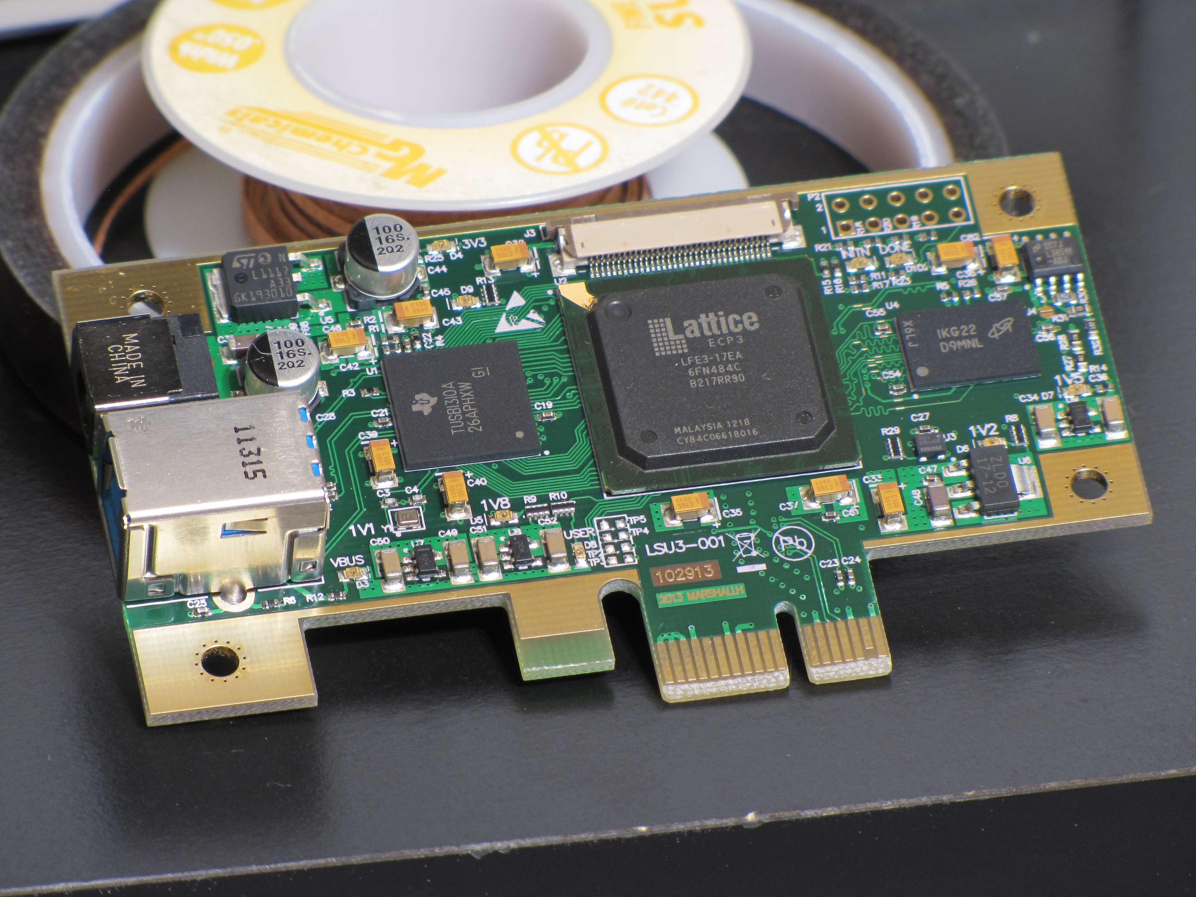
[08:50:48] <The_Coolest> http://i.imgur.com/NkRWoqT.jpg?2
[08:50:51] <The_Coolest> :D
[08:51:12] <The_Coolest> look at the usb connector, no soldermask = fail
[08:52:29] <DanFrederiksen> http://www.zev.dk/design/DCcr1/Boardpop.jpg
[08:52:41] <RikusW> ask hackvana about pcbs
[08:53:12] <The_Coolest> DanFrederiksen>> Pretty!
[08:53:19] <DanFrederiksen> thx :)
[08:53:23] <RikusW> I do remove soldermask between tqfp pins as a precaution for misaligned masks
[08:53:31] <DanFrederiksen> but you have soldermask on the TQFP so can't be process
[08:54:05] <DanFrederiksen> I'd think
[08:54:09] <The_Coolest> DanFrederiksen it's weird, it only has soldermask there because of the 45� angle
[08:54:21] <DanFrederiksen> btw my text was a little messed up too
[08:54:25] <DanFrederiksen> size and place was wrong
[08:54:48] <The_Coolest> DanFrederiksen the pcb house can't do soldermask thinner than 0.2mm
[08:55:20] <DanFrederiksen> what's the gap on the usb?
[08:55:26] <The_Coolest> i had soldermask swell set to 0.1mm, so it got screwed up.
[08:55:35] <The_Coolest> 0.3mm
[08:56:21] <The_Coolest> do you use a reflow oven? those solder joints are awsome
[08:57:04] <The_Coolest> what does that board do, btw? 320V/320A what? :p
[08:57:28] <DanFrederiksen> I don't think there is any solder in that picture :)
[08:57:41] <DanFrederiksen> but I use paste and now I have a hot air gun
[08:57:46] <The_Coolest> lol just fit testing?
[08:57:57] <DanFrederiksen> yep, for the extreme reason :)
[08:58:03] <The_Coolest> cool. I need to get one
[08:58:18] <DanFrederiksen> Atten 858D+, dirt cheap and works
[08:58:28] <The_Coolest> I can solder a tqfp with an iron, can't remove one tho
[08:58:56] <DanFrederiksen> yeah I soldered that board with iron too but I figure hot air is just cooler
[08:59:09] <The_Coolest> mhm
[08:59:18] <DanFrederiksen> laser even cooler :)
[08:59:58] <The_Coolest> I'm considering building an HV programmer for AVRs
[09:00:06] <The_Coolest> but USB powered only
[09:00:16] <RikusW> A thickish piece of copper wire soldered to all pins might work to remove it.
[09:00:23] <DanFrederiksen> the board is a controller for electric car power electronics
[09:00:39] <RikusW> The_Coolest: I already have
https://sites.google.com/site/megau2s/
[09:00:41] <DanFrederiksen> DC motor
[09:00:59] <The_Coolest> RikusW fu :( :p
[09:01:04] <moemoe> phinxy: only toggle a led in the main loop for test reasons, and make sure that works.
[09:01:19] <moemoe> probably the problem is somewhere else
[09:03:26] <The_Coolest> RikusW why do you need so many modules?
[09:05:04] <RikusW> those are optional extras
[09:05:41] <beaky> hello
[09:05:41] <RikusW> ordinarily I power the AVR via ISP using only the U2S board
[09:05:42] <The_Coolest> you wrote the firmware and all yourself?
[09:05:47] <beaky> what is the differnec ebetween ATmega and ATxmega
[09:05:51] <RikusW> yep
[09:05:51] <RikusW> all in asm
[09:05:58] <The_Coolest> damn.
[09:06:02] <The_Coolest> you're nuts
[09:06:10] <RikusW> heh :)
[09:06:25] <The_Coolest> beaky> a lot
[09:06:37] <RikusW> beaky: xmega got more peripherals and some advanced functionality
[09:06:43] <RikusW> its still 8 bit avr though
[09:07:16] <beaky> i love 8-bit avr
[09:07:24] <beaky> avr is the best 8-bit mcirocntorler
[09:07:26] <RikusW> The_Coolest: I got the jtagice mki and stk500 firmware and disassembled it
[09:07:32] <RikusW> so I can do OCD too
[09:07:52] <The_Coolest> :o
[09:08:00] <The_Coolest> on-chip debugging?
[09:08:05] <RikusW> yep
[09:08:10] <The_Coolest> nice
[09:08:37] <RikusW> the source for the jtag is on the site along with the disasm
[09:08:47] <RikusW> it can be compiled to run on any avr
[09:09:28] <RikusW> its mki only, so will only work with AS4 not 5 or 6
[09:09:45] <RikusW> it does support programming newer avrs though
[09:09:58] <The_Coolest> RikusW add PDI support if you haven't yet
[09:10:11] <RikusW> avrdude and avarice will need some hacking to support it though
[09:10:27] <RikusW> I'll look into pdi sometime
[09:10:55] <RikusW> http://www.ruemohr.org/docs/debugwire.html
[09:10:56] <The_Coolest> it seems to be a half duplex uart basically
[09:11:11] <RikusW> I already hacked dW
[09:11:50] <RikusW> PDI programming is described in the datasheets, but not the debugging part
[09:12:31] <RikusW> connecting a sync uart rx line to the dragon and avr should give a nice dump
[09:12:39] <RikusW> thats about how I did dW
[09:13:15] <The_Coolest> :o
[09:14:34] <RikusW> btw my programmer supports disabling the dW fuse for unbricking, and its automatic
[09:14:48] <The_Coolest> nice
[09:14:59] <RikusW> you won't even notice DWEN was enabled, unless you forget the 10k reset pullup....
[09:15:41] <RikusW> its actually very simple, for temp disable of dW send 0x06 at the right baud to the reset pin
[09:16:06] <RikusW> default dW baud = clock / 128
[09:16:25] <The_Coolest> you need HV for that?
[09:16:31] <RikusW> no
[09:16:43] <RikusW> only bitbanged dW uart
[09:16:44] <The_Coolest> hmmm
[09:17:11] <RikusW> dW autobauds as well
[09:17:17] <The_Coolest> dW is one-wire, right? there's no clock?
[09:17:25] <RikusW> yes
[09:17:34] <RikusW> after you let reset go high the avr send 0x55
[09:17:58] <RikusW> that is how the Atmel tools detect the baud
[09:18:58] <The_Coolest> cool
[09:20:15] <PoppaVic> It'd be nice to get a decent programmer (I prefer 'blower') for cheap.. The price-ranges on this stuff is nuts
[09:21:30] <The_Coolest> agreed
[09:21:40] <The_Coolest> what's 'blower'?
[09:44:56] <phinxy> moemoe, you were right. i printed the output ouside the LCD somehow
[10:00:47] <hackvana> DanFrederiksen: Hi!
[10:01:45] <hackvana> Boards through me can have silkscreen down to 4mil guaranteed.
[10:02:05] <hackvana> (I have to go soon, 2:30am here)
[10:09:13] <hackvana> DanFrederiksen:
https://secure.flickr.com/photos/suigetsu/11760907484/sizes/l/ http://imageshack.us/a/img201/5203/all9.jpg https://www.dropbox.com/sc/oz7xxnf05vhn79x/GAh1nLfmLl https://secure.flickr.com/photos/suigetsu/11865089496/sizes/l/ :-)
[10:10:33] <hackvana> I'm going now, bye!
[10:37:00] <phinxy> byee
[10:42:06] <phinxy> I was forced to set both OCIE2A and OCIE2B in a timer or otherwise it crashed after a couple seconds.. Any reason i just cant use one?
[10:49:38] <phinxy> ooh. i guess i need a top and a bottom (OCR1A&B) for it to work