Back
[00:37:57] <mimcpher> inflex has the right idea I think. Unless you are using the timer for something else too
[00:38:50] <mimcpher> You could change the config register to disable pwm too.
[00:45:51] <rue_mohr> he wants to be abel to do it by changing 1 bit, so that he can focus on the code that does the rc6 encoding
[00:47:23] <inflex> well, disabling the timer only requires 1 bit
[00:49:02] <rue_mohr> oo you could stop the clock source
[03:22:48] <DarkSector> In order to call functions do I need to manually setup the stack pointer? in ASM?
[03:22:57] <OndraSter> yes
[03:23:24] <DarkSector> and how exactly do I do that, is there a small example that I could use?
[03:23:32] <OndraSter> on the beginning of your file
[03:23:40] <OndraSter> LDI R16, LOW(RAMEND)
[03:23:43] <OndraSter> OUT SPL, R16
[03:23:48] <OndraSter> LDI R16, HIGH(RAMEND)
[03:23:51] <OndraSter> OUT SPH, R16
[03:24:08] <DarkSector> so that just automatically sets the stack pointer?
[03:24:12] <DarkSector> oh yeah obvioulsy
[03:24:14] <OndraSter> (that is for devices with > 256B RAM, the small attinys have only SPL)
[03:24:17] <OndraSter> yep
[03:24:18] <DarkSector> okay
[03:24:33] <OndraSter> brb 10 minutes
[03:24:36] <DarkSector> nice, let me try that
[03:32:50] <OndraSter> (back in the business)
[04:18:00] <OndraSter> I am wondering how many external interrupts has our brain?
[04:47:32] <CapnKernel> OndraSter: Not sure, but seems to be a lot when exams are on :-)
[04:47:40] <OndraSter> :D
[04:47:41] <OndraSter> yep
[04:47:51] <OndraSter> still haven't started learning -.-
[08:32:03] <Xata> sup
[08:33:55] <Xata> Guys, maybe somebody knows ready-to go solution. i need a tranny on r/2r dac for atmega. 5v, maybe some general-purpose stuff?
[08:35:34] <OndraSter> you need a tranny?
[08:36:07] <OndraSter> (jk)
[08:36:10] <Xata> OndraSter: transistor. as i understood this means a shortcut to transistor in english
[08:36:13] <OndraSter> just check any r2r dac :)
[08:36:17] <OndraSter> oh
[08:36:46] <OndraSter> so it will be connected to tranzistor,
[08:37:01] <Corwin> Xata... put "tranny" in google image search to find out what tranny is :)
[08:37:10] <OndraSter> transmission! :D
[08:37:12] <Xata> OndraSter: and transistor's output wil be to FET
[08:37:25] <OndraSter> so it will be DAC -- BJT -- FET?
[08:37:58] <Xata> Corwin: i know about tranny, oh god how i know about it. but i thought it means transistor also as a joke
[08:39:01] <Xata> OndraSter: a32 -- R/2R -- BJT (BC547?) -- FEP101B - soviet fet)
[08:39:34] <OndraSter> well then, make R2R DAC with opamp attenuator so it goes 0 - 0.6V
[08:39:36] <OndraSter> :)
[08:39:39] <OndraSter> scale
[08:39:40] <Xata> *FET (2p101b - soviet fet)
[08:40:52] <Xata> OndraSter: but i need 0-5v. my fet has this range. not fat fet
[08:41:08] <OndraSter> yes, but BJTs have 0 - 0.6V to fully open
[08:41:28] <CapnKernel> trannie can also be transformer
[08:41:41] <OndraSter> never heard "trannie" as transformer before, CapnKernel
[08:42:04] <Xata> so it's trannie, not tranny :D
[08:42:14] <CapnKernel> So, you had a blackout last week? Yeah, car hit a pole and wiped out the tranny
[08:42:17] <CapnKernel> 都可以
[08:42:43] <Xata> keke
[08:43:01] <Xata> CapnKernel: what was said in second message? utf-8 garbage <_<
[08:43:22] <Corwin> my client says it was "All OK" in chinesse
[08:43:23] <CapnKernel> Chinese for "either way"
[08:43:34] <OndraSter> oh
[08:45:39] <Xata> OndraSter: any trannIE what will be full-open on 5v?
[08:46:04] <OndraSter> duh, not from top of my head
[08:46:49] <Xata> nah. fetching from dac straight to fet is not ok, as far as i get it.
[08:47:03] <OndraSter> well you usually need some opamp to buffer this output
[08:47:18] <OndraSter> so why not use opamp as a voltage follower and feed the DAC with output from the opamp?
[08:47:27] <OndraSter> unless we are talking high frequency switching then the opamp will be just fine
[08:48:18] <Xata> OndraSter: not too high frequency. so what type of op-amp circuit i use for this? instead of transistor
[08:48:28] <Xata> amplifier?
[08:48:38] <OndraSter> yes, regular opamp
[08:48:55] <OndraSter> voltage follower
[08:49:06] <OndraSter> you connect it as a voltage follower*
[08:49:12] <OndraSter> since your R2R DAC goes 0 - 5V as well
[08:49:24] <Xata> OndraSter: so i google voltage follower? got it.
[08:49:38] <OndraSter> ye
[08:50:48] <Xata> OndraSter: just feedback? out to minus? i can do THAT MAD STUFF :D
[08:50:53] <OndraSter> :)
[08:51:03] <OndraSter> what is on the input is on the output
[08:51:16] <OndraSter> look for rail2rail opamps though!
[08:51:53] <OndraSter> rail to rail
[08:53:54] <Xata> OndraSter: wait a minute. i saw one thing... so i can use op-amp for amplitude modulation? i feed carrier to - and modulator to plus - and i get AM? without that fet stuff?
[08:54:19] <OndraSter> no idea mate
[08:54:57] <OndraSter> but I suppose so
[08:55:22] <Xata> This has to be
[08:55:26] <Xata> SIMULATED
[08:55:30] <Xata> YEAAAAAAAAAAAAAH
[08:55:34] <OndraSter> yep
[08:55:35] <OndraSter> ltspice?
[08:55:36] <Xata> :B
[08:55:49] <Xata> OndraSter: Proteus
[08:55:57] <Xata> ISIS
[08:56:36] <Xata> OndraSter: thanks god nobody still cares here do you have legal soft or not
[08:56:49] <OndraSter> as long as nobody asks..
[09:14:44] <Xata> OndraSter: why so?
http://img204.imageshack.us/img204/7728/modulatetest.png
[09:15:59] <OndraSter> remember what I said? :)
[09:16:09] <OndraSter> <OndraSter> look for rail2rail opamps though!
[09:17:05] <Xata> OndraSter: naaah... thanks for advice, anyway
[09:20:28] <OndraSter> what naaaah?
[09:20:31] <OndraSter> r2r are common
[09:47:05] <razec> http://www.engadget.com/2012/05/22/google-officially-closes-deal-for-motorola-mobility/
[11:22:40] <chupas> where can you download Studio 5 now adays
[11:22:48] <chupas> atmel website just sends you to 6
[11:23:22] <Tom_itx> why do you want 5?
[11:24:00] <chupas> people here have said 6 still has issues
[11:24:11] <chupas> i dont with to deal with issues right now
[11:24:17] <Tom_itx> and 5 doesn't?
[11:24:30] <chupas> If it does I know how to work around them
[11:24:44] <chupas> as it is what ive been using
[11:24:54] <Tom_itx> i could stick it on my server i guess
[11:25:03] <Tom_itx> if you can't find it
[11:26:22] <Tom_itx> they have a studio archive
[11:26:34] <Tom_itx> http://www.atmel.com/tools/STUDIOARCHIVE.aspx
[11:26:45] <OndraSter> Tom_itx, yes, as6 has issues that 5.1 doesn't :P
[11:26:47] <Tom_itx> you're all set
[11:26:48] <OndraSter> I reported two bugs
[11:27:00] <chupas> AHh ther we go, thx
[11:27:34] <Tom_itx> it was a link off their studio page
[11:27:36] <Tom_itx> fwiw
[11:27:48] <Corwin> why do i always get my hands on nice LCD displays when i cant find anything useful about them on net?
[11:28:04] <Tom_itx> graphic?
[11:28:10] <Corwin> yes
[11:28:22] <Tom_itx> well, search for the controller
[11:28:35] <Corwin> there is no label on that one
[11:28:52] <Corwin> and i cant anything about display from laptop either
[11:29:01] <vsync_> i dont even
[11:29:10] <Corwin> just lot of china sellers selling that lcd module
[13:58:38] <mitsakos> hello, i'm trying to select the second digit from the end of the following decimal number. eg. 1234 -> 3
[13:58:55] <mitsakos> what i'm doing is temp=(decimal/10)%10;
[13:59:10] <mitsakos> by this it is supposed to have the number 3
[13:59:57] <mitsakos> but if i use temp variable in the program to check it or move it to other variable the mcu resets
[14:06:20] <OndraSter> full code, mitsakos ?
[14:06:34] <mitsakos> it is complicated
[14:12:43] <OndraSter> hmm
[14:12:49] <OndraSter> red LEDs shine more than green LEDs
[14:12:53] <OndraSter> @ the same current!
[14:14:15] <gidna> Hi
[14:15:20] <OndraSter> hi
[14:15:20] <tobbor> hi OndraSter.
[14:15:23] <OndraSter> OH GOD
[14:15:23] <OndraSter> hi
[14:15:24] <OndraSter> hi
[14:15:24] <tobbor> OndraSter! like, totally tell us about the project!
[14:15:24] <tobbor> OndraSter! like, totally tell us about the project!
[14:15:24] <OndraSter> hi
[14:15:24] <OndraSter> hi
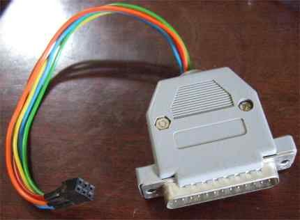
[14:16:06] <gidna> I would like to build this programmer
http://digital-day.webs.com/parallel_programmer_atmega.JPG I have only a female jack not a male one like in the picture. How can I do?
[14:16:33] <Corwin> hardly
[14:16:43] <Corwin> go buy correct jack
[14:16:45] <OndraSter> you can try operation
[14:16:53] <Corwin> :D
[14:16:55] <OndraSter> make male out of female
[14:17:52] <gidna> How?
[14:18:00] <RikusW> ask hackkitten how :-D
[14:18:24] <OndraSter> gidna, go to local hospital and ask them "I'd like some "male implants" if you know what I mean!"
[14:18:26] <OndraSter> :P
[14:18:35] <drgreenthumb> 0-\
[14:18:47] <gidna> Can't just instert resistors in the hole of the female jack??
[14:18:55] <OndraSter> you can
[14:19:37] <specing> RikusW: Hahahah
[14:19:46] <Corwin> basicaly you can just put wires with resistors directly to your printer port on your pc, and use some glue/tape to fix it in place
[14:19:56] <izua> classy
[14:21:34] <Corwin> gidna... i know it will sound like stupid question... but does your computer have printer port?
[14:22:27] <gidna> Corwin, sure...
[14:23:02] <Corwin> its just... i know someone who put great effort building stk200 dongle... then realizing his laptop has no LPT port :)
[14:23:43] <Steffanx> Ha
[14:24:22] <mitsakos> OndraSter yes color leds draw different current depending on the color
[14:24:34] <OndraSter> that's why they are driven by constant current
[14:24:41] <Steffanx> :P
[14:24:42] <OndraSter> Corwin, yourself? :D
[14:24:47] <Corwin> nope
[14:24:53] <OndraSter> anyway, the problem is human eye
[14:25:16] <gidna> Corwin, How can I do??
[14:25:55] <Corwin> i bought stk200 from Kosta@mcu, then used it to build AVR910 clone, which i later used to build STK500 clone from tuxgraphics... then i moved to dragons
[14:26:43] <gidna> Corwin, How can I build this
http://www.scienceprog.com/wp-content/uploads/2008/05/avr_isp_programmer.jpg ?
[14:26:55] <gidna> It seems it has no resistors at all
[14:27:05] <Corwin> resistors hidden inside connector
[14:27:18] <Corwin> inside the gray case of conector
[14:27:43] <gidna> ok..there only few cables than pins on the jack...
[14:28:43] <Corwin> well you already postet the schematics
[14:28:55] <Corwin> count the wires there
[14:29:28] <gidna> yes but for example here
http://circuitgizmos.com/wordpress/?p=272
[14:29:44] <gidna> it bends pins of the male jack.. I tould you I have the female..
[14:30:00] <Corwin> female is PC part
[14:30:10] <Corwin> you need male to be able to connect/disconnect it from pc
[14:30:43] <gidna> yes but in the cable one is male and the other female..
[14:31:14] <Corwin> where is female ?
[14:31:47] <gidna> on the cable..and pc
[14:32:28] <Corwin> yes, your dongle (the thing you want to build) will use male connector, to connect to female counterpart on your pc
[14:32:41] <Corwin> i dont understand your problem here
[14:33:04] <karlp> the problem is trying to use a parallel port in the first place
[14:33:14] <Corwin> :D
[14:33:23] <karlp> this isn't 1993.
[14:33:42] <Kevin`> I bet you think it's wrong to use a serial port too? ;p
[14:34:03] <karlp> not outright wrong, but I'd normally prefer to use usb, yes.
[14:34:14] <karlp> serial's not nearly as much of a hassle as parallel ports.
[14:34:57] <Kevin`> so would I in theory, but usb doesn't work in some cases, like debugging, and usb has higher latency (important for the parallel port, less important for normal usage of serial though)
[14:35:56] <karlp> he's asking about building a bit banging programmer.
[14:36:15] <karlp> not a scanner/printer interface, or a high speed debugger
[14:36:48] <Kevin`> parallel port certainly works for that, but i'd rather use a usb microcontroller these days (screw the fact that you can't program it without itself)
[14:37:31] <RikusW> Kevin`: the mega32u2 does have the flip bootloader on it by default
[14:37:57] <Kevin`> oh, true
[14:40:10] <specing> You need the parport/serial one for bootstraping the usb one
[14:40:57] <RikusW> specing: it already comes with a flip bootloader
[14:41:09] <RikusW> Atmel loads it in the factory
[14:41:21] <Corwin> or one can spend few dolars on usbasp clone, like
http://www.ebay.com/itm/1PCS-USBasp-USBISP-3-3V-5V-AVR-Programmer-USB-ATMEGA8-New-/261021924011?pt=LH_DefaultDomain_0&hash=item3cc61e7aab
[14:41:52] <specing> Ah
[14:42:04] <Kevin`> or a few more dollars and get an avrdragon or similar
[14:42:11] <specing> Well I remember I bootstrapped my USBtinyISP that way
[14:42:37] <Corwin> dragon is $49 afaik... bit more than few
[14:44:37] <RikusW> and Tom_itx and me also have programmers
[14:45:12] <RikusW> http://sites.google.com/site/megau2s/home
[14:45:46] <Corwin> green pcb and big ugly usb jack?
[14:46:24] <karlp> what's wrong with green?
[14:46:48] <RikusW> I'd rather have a big strong jack than a tiny one
[14:46:56] <specing> RikusW: Does your programmer do simultaneus programming/serial now?
[14:50:32] <RikusW> specing: That can be added seperately, I don't really want to modify the STK500 code now anymore, is more or less bug free...
[14:51:30] <RikusW> specing: but the mode can be changed to UART and back to STK500 as it is
[14:52:40] <RikusW> and I have added a SPI tx command to the STK500 code long ago
[14:53:25] <RikusW> Actually I used CMD_SPI_MULTI and just added commands to turn on/off SPI without entering programming mode
[14:58:40] <Steffanx> Time to start using C RikusW :P
[15:03:58] <RikusW> time to paste another url I think ? :-P
[15:05:08] <Steffanx> Noo
[15:50:44] <OndraSter> I don't understand this. On LPC1768 they have got four ports (32bit) where:
[15:50:52] <OndraSter> Port0 is complete EXCEPT pins 12 13 14 and 31
[15:51:06] <OndraSter> Port1 is complete EXCEPT pins 2 3 5 6 7 11 12 and 13
[15:51:23] <OndraSter> Port2 contains pins only 0 - 13
[15:51:34] <OndraSter> Port3 contains pins only 25 and 26
[15:51:39] <Tom_itx> what the hell do you want? all of it???
[15:51:39] <OndraSter> Port4 contains pins only 28 and 29
[15:51:40] <OndraSter> WTF
[15:51:49] <OndraSter> I don't understand why they have 4 partial ports
[15:51:51] <OndraSter> instead 2 full ones?
[15:52:01] <Corwin> 4 > 2
[15:52:03] <Corwin> thats why
[15:52:05] <OndraSter> heh
[15:52:17] <OndraSter> I am not sure that marketing works here :P
[15:52:25] <OndraSter> plus one pin with "no connection"!
[15:52:56] <OndraSter> gimme more pins bollocks :P
[15:53:02] <OndraSter> it is TQFP100!
[15:56:19] * RikusW wonders for what possible reason they use 4 ports instead of 1 or 2
[15:58:40] <specing> Or why they need power/GND pins on every side (and all have to be connected)
[15:58:54] <specing> Makes board design a nightmare :/
[15:59:21] <OndraSter> I understand having ground on each side
[16:02:05] <karlp> man, the letter of the ports has almost no connection to anything useful anymore.
[16:02:26] <karlp> also, OndraSter, there are other channels that talk about arm a lot more often
[16:02:43] <OndraSter> I know
[16:02:45] <OndraSter> but I like to rant
[16:04:04] <Kevin`> karlp: it lets you write a word-size value in a single instruction
[16:04:35] <Kevin`> for use with parallel peripherals or memory or similar
[16:05:40] <karlp> oh, fair enough. I haven't done much where I needed to write so many bits at once :)
[16:06:07] <karlp> normally if you want that many bits at once yo uhave an sdram controller though right?
[16:07:50] <specing> that is there only because you need to refresh that crap
[16:08:53] <Kevin`> karlp: if the device behaves like sram/sdram with address+data, and the chip has a controller, that's useful too
[16:21:24] * RikusW just saw and 8bit addressable chip MC14599B
[16:21:49] <RikusW> 8 bits of ram anyone ? :-P
[16:22:09] <izua> are they made with transistors? :D
[16:22:24] <RikusW> its cmos
[16:22:29] <izua> actually i think they might be 256 x 8?
[16:22:40] <RikusW> no, only 8 bits
[16:22:52] <RikusW> and all 8 bits are wires to pins
[16:22:53] <izua> so, like a octal d latch? o_O
[16:23:09] <RikusW> not quite, there is 3 address lines
[16:23:23] <RikusW> and 1 data line
[16:23:51] <izua> lol
[16:23:53] <izua> that's so pointless
[16:25:04] <RikusW> its used inside an old two way radio to enable/disable channels for scanning
[16:25:33] <RikusW> there is like 14 ic's on the channel scan board
[16:25:45] <RikusW> a single attiny could do all that and more
[16:26:40] <RikusW> izua: its called an 8bit addressable latch
[16:27:23] <OndraSter> :D
[16:28:04] <RikusW> a shift register would be way more usefull connected to SPI
[16:29:20] <izua> i guess it's useful if you want to spare pins
[16:37:01] <OndraSter> USB was invented by evil people
[16:37:07] <OndraSter> who else would make the connector so bad?
[16:37:15] <OndraSter> srsly, how many times do you manage to put in the cable on the first time?
[16:37:17] <OndraSter> (without looking)
[16:39:21] <Kevin`> OndraSter: significantly higher than 50% of the time
[16:40:13] <Steffanx> OndraSter has eyes he doesn't like to use?
[16:40:13] <OndraSter> lucky you
[16:41:14] <Steffanx> You always try to use the RJ45-port for you USB cable, don't you OndraSter ?
[16:41:32] <OndraSter> yes, I once stuck my USB flash drive to ethernet (without looking) and wondering why it doesn't work
[16:41:34] <OndraSter> lol
[16:41:46] <dfletcher> heh I've done that in laptops. it actually fits :/
[16:41:57] <OndraSter> when you have your PC turned to the wall, you don't usually peek at the computer's IO shield.
[16:42:02] <dfletcher> I'd have to agree, the cable isn't great.
[16:55:45] <OndraSter> wow
[16:55:54] <OndraSter> I tried uploading my picture made for 2bit colors
[16:56:03] <OndraSter> aka 4 views that were switching
[16:56:07] <OndraSter> (talking about my LED box)
[16:56:20] <OndraSter> I tried uploading the same picture with 8 views and much more color depth
[16:56:27] <OndraSter> and one can see difference even between 5 and 6 views!
[16:56:32] <OndraSter> even 6 vs 7 can be seen a little
[16:56:41] <OndraSter> I wasn't expecting that!
[16:56:51] <OndraSter> my teacher told me "about 3 or 4 tops"
[17:27:58] <karlp> OndraSter: you nkow that the usb logo is always on the same side of the plug right? (well, it's meant to be, but enough of the time to be helpful)
[17:28:17] <OndraSter> what are we talking about right now?
[17:35:12] <OndraSter> DUH it is 0024
[17:35:18] <OndraSter> it was 2100 an hour ago!
[17:35:28] <OndraSter> by my internal clock
[17:51:52] <specing> indeed
[17:53:11] <Tom_itx> ADC12Dxx00RF ADCs are the industry's first direct RF-sampling ADCs that can directly sample frequencies beyond 2.7 GHz at up to 3.6 GSPS
[17:54:10] <OndraSter> how much?
[17:54:16] <OndraSter> (if I have to ask, I don't have that money I presume)
[17:54:28] <OndraSter> who makes them btw?
[17:54:32] <dfletcher> handy for scanning for the aliens.
[17:54:56] <Tom_itx> http://www.ti.com/ww/en/analog/dataconverters/gigadc/rf-sampling.shtml
[17:56:45] <OndraSter> Tom_itx, do they send samples of this? :D :D
[17:57:03] <Tom_itx> i think ti is pretty good about samples
[17:57:08] <OndraSter> yes
[17:57:13] <OndraSter> they used FedEx
[17:57:19] <OndraSter> it took 36 hours from samples order to get them here
[17:57:22] <OndraSter> to the other side of the planet
[17:57:28] <OndraSter> quite amazing
[17:57:32] <OndraSter> I ordered one chip, 5 pcs lol
[17:57:42] <Tom_itx> they thought you were serious
[17:58:01] <OndraSter> well I was
[17:58:02] <dfletcher> hmm I wonder if my okw sample enclosures will show up soon. ordered on Sunday :)
[17:58:05] <OndraSter> I even told them I am student :)
[17:58:16] <Tom_itx> df, not hammond?
[17:58:32] <dfletcher> Tom_itx, nah I liked those blob enclosures from okw
[17:58:39] <Tom_itx> OndraSter they get you while you're young
[17:58:49] <OndraSter> sure
[17:58:51] <dfletcher> the one called "Unit" will make a nice remote I think
http://www.okwenclosures.com/products/okw/blob.html
[17:58:52] <OndraSter> and you know their offers
[17:58:59] <OndraSter> and they know you will use it when you grow up :)
[18:00:20] <Tom_itx> http://www.ti.com/tool/adc12d1800rfrb
[18:00:37] <Tom_itx> only 995
[18:00:43] <OndraSter> not bad!
[18:00:51] <OndraSter> if I had extra penny I would buy it!
[18:01:36] <OndraSter> surprisingly there is Xilinx FPGA on the board
[18:02:09] <Tom_itx> also a cradle robber
[18:12:37] <iR0b0t1> I'm having problems setting the prescaler for Timer 2 on an atmega328
[18:13:03] <iR0b0t1> TCCR2B |= ~_BV(CS22) | _BV(CS21) | ~_BV(CS20);
[18:13:08] <iR0b0t1> that should be div 8
[18:13:26] <iR0b0t1> with a clock of 16MHz and a compare of 0x24, it should produce a 56kHz out
[18:13:31] <iR0b0t1> it gives me 220Hz
[18:13:35] <iR0b0t1> or 212Hz
[18:14:01] <Tom_itx> does _BV set or read?
[18:14:20] <Tom_itx> i don't like using those things
[18:14:20] <iR0b0t1> _BV expands to (1 << value)
[18:14:29] <Tom_itx> i'd rather see it that way
[18:14:36] <iR0b0t1> okay
[18:14:48] <Tom_itx> but i don't care what you do
[18:15:20] <OndraSter> is it 8 or 16bit timer?
[18:15:32] <Tom_itx> i think 2 is 16
[18:15:38] <iR0b0t1> 8
[18:15:55] <OndraSter> hm really? I thought that 0 is 8bit and the rest is 16bit
[18:15:56] <OndraSter> let me check
[18:16:28] <OndraSter> hmm it is really 8bit
[18:16:29] <Tom_itx> 8 bit
[18:16:29] <OndraSter> wow
[18:17:01] <OndraSter> well
[18:17:07] <OndraSter> CS22 CS21 CS20 is /1024
[18:17:09] <iR0b0t1> This is really annoying. How else would I set it? Why does it not seem to be working?
[18:17:24] <OndraSter> /8 is CS21
[18:17:25] <OndraSter> only
[18:17:25] <iR0b0t1> ~_BV(CS22) | _BV(CS21) | ~_BV(CS20);
[18:17:29] <iR0b0t1> note ~
[18:17:30] <OndraSter> yes
[18:17:36] <OndraSter> oh
[18:17:42] <OndraSter> I hate that style!
[18:17:57] <OndraSter> why not just write (1 << CS21)
[18:18:03] <OndraSter> instead that... oh ignore me
[18:18:05] <iR0b0t1> regardless, just using CS21 doesn't work either
[18:18:14] <OndraSter> check fuses?
[18:18:40] <iR0b0t1> How
[18:18:41] <iR0b0t1> ?
[18:18:45] <OndraSter> through programmer
[18:18:53] <iR0b0t1> And just using TCCR2B |= _BV(CS20); gives me no output at all
[18:18:55] <OndraSter> to make sure you are running on external 16MHz
[18:18:58] <iR0b0t1> I don't have a programmer
[18:19:05] <OndraSter> bootloader?
[18:19:08] <iR0b0t1> I'm using an atmega with the arduino bootloader
[18:19:12] <OndraSter> oh
[18:19:25] <OndraSter> how do you measure the frequency?
[18:19:55] <OndraSter> and what about other registers? are you running in mode 0?
[18:21:01] <iR0b0t1> wait waht
[18:21:02] <iR0b0t1> what
[18:21:09] <iR0b0t1> I'm measuring the frequency with an oscilloscope
[18:21:14] <iR0b0t1> mode 0?
[18:21:31] <OndraSter> yes, WGM bits
[18:21:35] <OndraSter> part of TCCR2A
[18:21:43] <iR0b0t1> yes
[18:21:58] <OndraSter> are you sure you are measuring it correctly? 212 or 220Hz isn't anything near that could be somehow division of 16MHz
[18:22:09] <iR0b0t1> *shrug*
[18:22:41] <OndraSter> just making sure :D
[18:23:40] <Tom_itx> is wdt biting your ass?
[18:23:46] <iR0b0t1> Is there code somewhere for setting up timer 2 for PWM output on pin 3 port b?
[18:23:48] <iR0b0t1> Arduino pin 9
[18:24:00] <Tom_itx> iR0b0t1 i have some for a 128 should be quite similar
[18:24:32] <iR0b0t1> okay, if you would
[18:24:59] <Tom_itx> http://tom-itx.dyndns.org:81/~webpage/avr/mega128/pwm_test/8bit_timers/
[18:26:03] <Tom_itx> you may have to move the bits and registers around
[18:26:15] <Tom_itx> they're not consistent with that
[18:28:26] <Tom_itx> all 3 timers are there
[18:45:47] <OndraSter> why did IDA ask me whether I want to disassemble that file in 16 or 32bit mode when I selected 8086 procsesor?
[18:47:07] <iR0b0t1> what the FUCK
[18:47:11] <iR0b0t1> this makes no sense!
[18:49:51] <learningc> yay, I received my jtagice3
[18:50:10] <iR0b0t1> okay this is bullshit
[18:50:13] * iR0b0t1 walks away for a while
[18:50:51] <learningc> lol, have you used one to begin with, iR0b0t1 ?
[18:51:00] <iR0b0t1> ...?
[18:51:05] <iR0b0t1> No, I'm talking about setting up timers
[18:51:14] <iR0b0t1> not working after I follow the data sheet explicitly
[18:51:15] <iR0b0t1> sooo
[18:51:17] <iR0b0t1> fuck me I guess
[18:51:24] <Tom_itx> i'd rather not
[18:51:44] <Tom_itx> maybe my tut uses timer2
[18:51:47] * Tom_itx looks
[18:51:47] <learningc> iR0b0t1: which hole?
[18:52:30] <Tom_itx> iR0b0t1 my tut uses timer0 but the code should be the same
[18:52:36] <Tom_itx> m168
[18:52:47] <Tom_itx> http://tom-itx.dyndns.org:81/~webpage/how_to/atmega168/mega168_pwm_index.php
[18:52:53] <Tom_itx> both are 8 bit
[18:53:08] <Tom_itx> change the register names and it should work fine
[18:53:28] <OndraSter> show us the whole code, iR0b0t1
[18:56:35] <Tom_itx> gawd, i could mod my code for him and make it work
[18:57:12] * Tom_itx wanders off
[18:57:40] <learningc> iR0b0t1: what are you trying to do?
[19:04:33] <Tom_itx> learningc, pwm timer2 on a 328
[19:05:28] <learningc> mmm, how complicated can that be?
[19:05:40] <OndraSter> 2 or 3 registers
[19:05:42] <OndraSter> that hard
[19:05:47] <learningc> lol
[19:06:02] <learningc> he should check if his timer is working first
[19:06:39] <learningc> iR0b0t1: can't you watch if the timer increments?
[19:07:38] <learningc> iR0b0t1: you have a scope?
[19:07:41] <OndraSter> just post the whole code
[19:33:18] <profil> Hey guys, I'm having some problem with unsigned chars I think, I wrote this function which convert hsv to rgb color space, case 4: *r = t, *g = p, *b = v; break;
[19:33:21] <profil> case 5: *r = v, *g = p, *b = q; break;
[19:33:23] <profil> }
[19:33:29] <profil> ahh, darnit
[19:33:44] <profil> this function ->
http://codepad.org/goCDlYIl
[19:34:55] <profil> but when I use it with PWM on my atmega328P (arduino uno) I get flickers between the color fadings, I'm calling the function in a for loop like this, "hsvtorgb(i, 255, 255, &r, &g, &b);" where i goes from 0 to 360
[19:35:34] <profil> I'm guessing I get overflows on the unsigned chars, but I dont get this behaviour when running it on my pc