Back
[07:41:59] <tosmo> should it matter whether the global interrupt bit ist set ( sei() ) before or after i set an individual timer interrupt bit?
[07:42:25] <Kevin`> no
[08:27:05] <tosmo> i am trying do read serial data with an ISR(USART0_RX_vect) interrupt handler. I've set up a simple test case where i toggle an LED every time the ISR gets called. To my surprise, it gets called at a rate of 36.2kHz without me sending anything! Here's the code:
http://pastebin.com/Xw6SY0dB
[08:27:27] <tosmo> any clues why that happens?
[08:30:50] <CapnKernel> Do you have a pin in a floating state?
[08:31:06] <CapnKernel> What is the mode of the interrupt - edge triggered or level triggered?
[08:31:18] <CapnKernel> What are you doing to clear the interrupt
[08:31:42] <CapnKernel> Can you find a trivial serial program on the net and adapt it for your hardware? Does it work?
[08:35:04] <tosmo> CapnKernel: found the mistake. it was main() getting rerun at about that rate.. didn't know it would get looped
[08:35:30] <CapnKernel> tosmo: Well done
[08:35:41] <tosmo> (and i happened to toggle the pin rather than set it, because i thought this would be equivalent..)
[09:02:32] * amee2k scratches his head
[09:02:37] <Kevin`> tosmo: main could get rerun if you exited main or if you triggered an unhandled interrupt. or if you called main.
[09:02:55] <amee2k> if the spec sheet for a TRMS DMM says "AC bandwidth: 100kHz" ... what exactly does that mean??
[09:09:46] <desaster> 4
[09:09:51] <desaster> ups
[09:10:21] <Steffanx> 5
[09:10:22] <Steffanx> ups
[09:10:51] <amee2k> hermes > ups
[09:11:15] <Steffanx> Hé, amee2k is back alive
[09:11:36] <amee2k> occasionally
[09:11:39] <amee2k> accidentially
[09:11:45] <amee2k> somewhat
[09:12:09] <Steffanx> wb
[12:23:16] <O0ddity> Can anyone tell what can you do with a JTAG interface on an avr?
[12:24:56] <O0ddity> am i right in thinking its only use ful for testing each of the Pins(exculding the jtag ones) on the chip, by selecting a 2 pins and using one for input and one for output?
[12:25:22] <O0ddity> how fast can this be done?
[12:26:25] <O0ddity> could i use it to control an LCD hooked up to the avr that is being JTAGed
[12:33:39] <Kevin`> O0ddity: you could, I suppose. normally you use jtag to debug software though, the fact that you can set all of the registers manually is kind of secondary and used to aid debugging
[12:34:38] <Kevin`> O0ddity: unless you have extremely fast hardware (avrone maybe?), a few lines of code running on the microcontroller to translate input from usb or serial into lcd output will be faster.. might always be faster actually
[12:36:47] <O0ddity> sure, but im just woundering if i can use jtag for chip to chip communication and would it be fast enough for an lcd
[12:37:40] <O0ddity> also is it viable aussuming i have no idea what kindof chip i am JTAging
[12:40:33] <Kevin`> O0ddity: you can identify the specific chip you have by the hardware id it sends over jtag, but you'd need to know how to handle all the chips you would be working with
[12:41:08] <Kevin`> O0ddity: the high level protocol for debugging for avr chips isn't documented, so don't use it for chip to chip communication
[12:41:58] <O0ddity> allreally jtag will do that
[12:42:30] <O0ddity> well if i can identify the chip i might be able to SIP it
[12:43:28] <O0ddity> im fairly sure its a atmega128 though
[12:47:20] <RikusW> O0ddity: I'd rather use SPI or UART for what you're trying to do
[12:47:38] <RikusW> Kevin`: there is some docs on avr ocd jtag
[12:48:00] <O0ddity> yeh i know that using Uart would be much better
[12:48:06] <RikusW> Besides I disassemble the jtagice mki's firmware ;)
[12:48:34] <RikusW> and created a clone too
[12:49:09] <O0ddity> I am kinda clueless
[12:49:23] <Kevin`> RikusW: indeed, and that's awesome of you :D. I wouldn't use it as an integral part of a device design though (atmel should support it themselves if I have to do that)
[12:49:40] <RikusW> jtag on the avr is a for slave mode only...
[12:49:56] <RikusW> Kevin`: you've seen it on my site ?
[12:50:28] <Kevin`> RikusW: i've seen mention several times that you have reverse-engineered some of the debugging protocols. I keep forgetting specifics though :)
[12:50:34] <RikusW> Kevin`: who said its an integral part of the avr design ?
[12:50:44] <O0ddity> WikusW: Whats your site?
[12:51:04] <Kevin`> RikusW: O0ddity said he wanted to use it for chip-to-chip communication
[12:51:16] <RikusW> http://sites.google.com/site/megau2s/home
[12:51:35] <RikusW> I wouldn't use jtag for something like that....
[12:51:46] <O0ddity> it would actually be more like slave mode
[12:52:17] <RikusW> except programming and debugging and maybe the boundary scan chain
[12:52:38] <O0ddity> anyway... how do i even use JTAG? do i need a special device? or can i just use a serial port?
[12:53:14] <RikusW> jtag is almost like SPI but with another line (TMS)
[12:53:23] <Kevin`> you need a special device. well, unless you use RikusW's work, in which case you need a capable general-purpose device
[12:53:29] <RikusW> you can read more about it in avr datasheets
[12:53:50] <RikusW> my clone can run on any avr
[12:54:04] <RikusW> will need AVRStudio 4 to compile...
[12:54:12] <RikusW> 5 should work too
[12:54:18] <Kevin`> you could technically use a serial port for it, but only using the control lines (not the serial part), and you'd still need a dongle to adapt the voltage levels
[12:54:34] <RikusW> and it only works on older avrs like m128
[12:54:36] <Kevin`> and software for doing that for avr will be a bit sparse
[12:54:47] <RikusW> but thats a AS4 limit...
[12:55:09] * specing sees no real value in JTAG1
[12:55:17] <specing> s/1//
[12:55:40] <RikusW> specing: I've updated it a bit to program newer avr's too, not uploaded that yet...
[12:56:06] <RikusW> I think the debug protocols are the same for older and newer avr's
[12:56:07] <Kevin`> jtag is pretty good in theory. you can connect a single dongle to any number of devices and access them using a standard protocol. exactly what is superior to that ;p
[12:56:09] <specing> I mean,
[12:56:43] <specing> Having no debugger forces me into writing 100% correct code
[12:56:53] <specing> And Im getting rather good at it
[12:57:02] <RikusW> Kevin`: not exactly, avr atmega ocd is much different from xmega and AVR32 is different too
[12:57:33] <RikusW> about the only common jtag feature is boundary scan
[12:57:45] <RikusW> and then you still need the device bsdl files
[12:57:46] <Kevin`> RikusW: hence the "in theory". also the base protocol is the same, so you could actually DO that if all your chips are supported by the same software, eg openocd or similar
[12:58:25] <O0ddity> I have a SIP Programmer and an m32(not the usb kind), could make this JTAG device of yours RikusW?
[12:58:27] <RikusW> Kevin`: you probably mean the physical part and the state machine ?
[12:59:06] <RikusW> O0ddity: get a m8 or m328 to make the jtagice then you can use it with the m32
[12:59:27] <RikusW> jtagicemki officially only works with m16 m162 m32 m64 m128
[13:00:03] <Kevin`> RikusW: yes. assuming the avr protocol was documented or picking another chip with actual support, you could connect the same dongle to both an avr8 and and arm chip at the same time
[13:00:14] <Kevin`> RikusW: perhaps more realistically an arm chip and an fpga, heh
[13:00:40] <RikusW> the voltages would need to be the same....
[13:01:17] <RikusW> you could daisychain any devices together
[13:01:49] <RikusW> thoug the old jtagicemki supported avrs should be first in the chain or programming will be slower
[13:02:56] <RikusW> O0ddity: you'll need avarice on Linux or AS4 on windows AS5 don't support jtagicemki
[13:03:51] <RikusW> specing: I've written the dW uart tx code today ;)
[13:04:05] <specing> got autobauding working?
[13:04:13] <RikusW> not yet
[13:04:36] <OndraSter> http://www.energylabs.com.br/el/pr/get.php?arquivo=902
[13:04:37] <OndraSter> spanish anyone?
[13:04:40] <O0ddity> i have AS5 and WinAVR
[13:04:41] <RikusW> will do baud calculation on the pc first until I get it debugged
[13:05:06] <RikusW> O0ddity: you'll need AS4 for the jtagice mki
[13:05:20] <O0ddity> ok
[13:05:44] <RikusW> AS5 don't support it :(
[13:05:55] <specing> lol
[13:06:10] <specing> ATMELs own software doesen't support it
[13:06:14] <specing> Haha
[13:06:30] <RikusW> specing: I've don't some preliminary baud detection code, it will send the measurements to the PC for now
[13:08:21] <specing> RikusW: how are you doing it? Counting time between pinchange interrupts?
[13:08:23] <RikusW> specing: the plan is to put the soft uart on a avr and do all the dW protocol stuff on the PC
[13:08:38] <specing> That is a good plan
[13:08:54] <RikusW> about, but I don't have interrupts available in that code... :S
[13:08:59] <RikusW> so polling
[13:09:20] <specing> You should support running your code on a minimal ATmega, which is like...8Kb?
[13:09:34] <RikusW> due to the way I load modules on my board I can't use interrupts in them...
[13:09:56] <RikusW> specing: it compiles to about 360 bytes now
[13:10:06] <specing> You can do some of the protocol on the chip itself, but in the prototype stage you should do everything in an easy to debug environment
[13:10:13] <specing> RikusW: lol 360 :D
[13:10:17] <RikusW> so it just might run on attiny :-P
[13:10:25] <specing> RikusW: is it usb or serial?
[13:10:31] <specing> I guess regular serial
[13:10:38] <RikusW> usb, but is use the bootloader cdc code
[13:10:43] <specing> ah
[13:10:53] <specing> so those 360 bytes are a lie
[13:10:55] <specing> :D
[13:11:07] <RikusW> not if you use normal uart
[13:11:20] <RikusW> it should end up far below 1kb
[13:13:06] <RikusW> heck my jtagice mki is only 3600 bytes....
[13:13:33] <specing> well for comparison, my SMPS charging code is ~500 bytes (ADC int, pwm adjusting, uart transmission)
[13:13:54] <RikusW> specing: C or asm ?
[13:14:15] <specing> the ADC interrupt is C + 50 instructions in asm
[13:14:18] <Tom_itx> port that to a tiny 10
[13:14:29] <specing> GCC went on lsd :D
[13:14:49] <specing> Tom_itx: don't have one :D
[13:15:02] <Tom_itx> i do
[13:15:15] <RikusW> specing: didn't you mean meth ?
[13:15:30] <specing> Tom_itx: but it currently uses 2(ADC)+1(PWM)+1(UART TX) IO lines
[13:15:56] <specing> RikusW: I was refering to GCC's overuse of the 32-bit instructions LDS and STS
[13:16:06] <Tom_itx> i have 2 adc and 2 pwm, no usart
[13:16:25] <Tom_itx> or 1 adc and 3 pwm
[13:16:30] <Tom_itx> or 3 adc and 1 pwm
[13:16:44] <specing> Tom_itx: what?
[13:16:54] <Tom_itx> it only has 4 ip
[13:16:56] <Tom_itx> io
[13:17:01] <RikusW> specing: gcc's use of avr instructions isn't optimal....
[13:17:02] <specing> I need usart for WxPython graphing :D
[13:17:07] <Tom_itx> i don't
[13:18:28] <j4cbo> dear atmel
[13:18:43] <j4cbo> the mega32u4 can produce 12 pwm signals
[13:18:53] <j4cbo> why are these muxed onto only 8 i/o pins? :[
[13:19:40] <specing> LOL
[13:19:41] <Tom_itx> they did it for the marketing department
[13:21:16] <Tom_itx> they didn't figure anyone would actually want 12
[13:29:43] <OndraSter> ¿Hablas español?
[13:29:58] <OndraSter> anyone :)
[13:29:58] <j4cbo> fortunately i only actually need 7 in this application
[14:01:28] <specing> Hehe, my computer's usb ports do not care about the max power setting of connected deviced
[14:01:31] <specing> s*
[14:07:45] <RikusW> most don't afaik ;)
[14:12:20] <Casper> specing: most do not, most board have a trace fuse: when something between 2 and 50A will flow then the trace will vaporise
[14:13:31] <specing> these USB ports are rated for 1A continous
[14:14:42] <RikusW> Casper: I think many boards have a self resetting fuse
[14:15:14] <RikusW> its a largish flat smd device
[14:15:16] <Casper> RikusW: most just do not have any protection
[14:15:41] <Casper> hmmm
[14:15:56] <Casper> what is the store name where I went for the dryer element...
[14:18:01] <Casper> good it's there
[14:18:11] <Casper> now... to do shopping...
[14:21:06] <Kevin`> there are boards that have proper control according to the specs and will shutdown the port under adverse conditions. of course there are also boards that just have it wired up to power with no protection at all. your milage will vary.
[14:23:19] <OndraSter> mine ports shuts down when there is too high current
[14:23:21] <OndraSter> I tested it
[14:23:25] <OndraSter> I had small short on one board -.-
[14:23:32] <OndraSter> the USB cut power to it
[15:22:31] <O0ddity> http://pastebin.com/6kABfZzP
[15:22:50] <O0ddity> Can anyone tell me why this curciut is going high somtimes?
[15:23:10] <O0ddity> PORTB PIN0 that is
[15:23:26] <O0ddity> http://imgur.com/wdQk3
[15:24:36] <O0ddity> when i press the toggle switch, somtimes the PIN0 goes to LOW, as expected.
[15:25:02] <O0ddity> but somtimes it goes from 2.5V to 5V
[15:25:32] <O0ddity> shouldnt its only be set at 5V or 0V
[15:27:06] <O0ddity> http://pastebin.com/6kABfZzP is the code and the circuit diagram is the imgur link.
[15:27:57] <O0ddity> its total random
[15:32:25] <Tom_itx> what is the exercise for?
[15:32:43] <O0ddity> toggle and LED
[15:32:48] <O0ddity> i dono
[15:33:17] <Tom_itx> http://tom-itx.dyndns.org:81/~webpage/how_to/atmega168/mega168_howto_main_index.php
[15:33:19] <O0ddity> well now i slowed it doen it seems to hold the state When the button is presssed
[15:33:35] <Tom_itx> http://tom-itx.dyndns.org:81/~webpage/avr/c_bits/bits_index.php
[15:33:45] <Tom_itx> that was a fairly fast loop
[15:34:05] <O0ddity> but i sill think its really wierd that it was giving me 3 diffrent states froma digital pin
[15:34:09] <Tom_itx> it takes ~20-30ms for a switch to be debounced
[15:34:28] <Tom_itx> if you don't account for that it may very well be your problem
[15:34:44] <O0ddity> yeh there isnt a cap or anything on it
[15:35:06] <O0ddity> i actualyl wanted to see the debouce on the LED
[15:35:43] <O0ddity> *the bounce
[15:35:50] <Tom_itx> http://www.all-electric.com/schematic/debounce.htm
[15:36:19] <Tom_itx> you won't be able to see it that quick on an led with the naked eye i doubt
[15:36:29] <Tom_itx> you can see it on a scope
[15:38:51] <Kevin`> schmitt trigger debounce is normally overkill when you have a microcontroller. you can just accept all the random crap and filter it in software
[15:49:43] <O0ddity> ok i changed the if staement to if the bit is clear
[15:49:48] <O0ddity> instead of NOT
[15:50:08] <O0ddity> and used a 20 ms delay
[15:50:17] <O0ddity> so it works as a toggle for the LED
[15:52:00] <O0ddity> but... when the delay is off.. ie its still debouning,it only works somtimes...
[16:52:44] <izua> randomly run into qtouch
[16:52:59] <izua> anyone can explain what exactly sort of hardware i should hook up?
[16:53:10] <izua> or am i simply supposed to design buttons/wheels/sliders on the pcb?
[16:55:30] <OndraSter> izua, that's how I understand it. I would do some reading about the soldering masks if they can not block it (cheap itead/seed vs some profi manufacturer processes etc)
[17:17:57] <OndraSter> I am supertired, gn
[17:18:36] <izua> hmm
[17:18:41] <izua> qtouch is four.. touchscreens?
[17:18:47] <OndraSter> not really
[17:18:52] <OndraSter> qtouch is for touch boards :)
[17:19:02] <vectory_> more like ipod like controles
[17:19:45] <izua> ah wait, i think i drifted away from qtouch
[17:19:51] <izua> i'm reading on something about touchscreens
[17:20:20] <izua> so wait.. qtouch is a lib that enables all this nifty stuff with some spare pins? or some peripheral in the controller? or just a glorified dedicated IC?
[17:27:23] <Kevin`> library
[17:29:12] <izua> ah
[17:29:48] <izua> i'm still not very clear on how this works - does it need adc pins or something like that?
[17:30:50] <OndraSter> it requires pins specified by datasheet
[17:31:11] <izua> i've been messing around with an idea of designing something similar, but using photodiodes/ir sensors or led matrices for a fool-resistant keyboard
[17:31:30] <izua> but.. this is sort of better.. if you just design your buttons/wheels/etc on your pcb and connect it to an avr
[17:31:52] <OndraSter> :D
[17:31:53] <OndraSter> yes
[17:34:07] <izua> man.. this is neat
[17:35:05] <izua> i can't find a lot of tech info though, is this out yet?
[17:37:39] <OndraSter> sure
[17:38:50] <OndraSter> again - gn
[17:38:58] <izua> sleep well
[17:39:05] <OndraSter> will do lol
[17:53:39] <Kevin`> izua: I think it works with normal io pins, no special requirements
[17:55:52] <izua> am i wrong to believe that a keyboard made with capacitive technology has a much longer life (think clicks per button, etc) and that, given the top panel is insulated, it's.. almost indestructible without a hammer or serious shock?
[17:56:22] <izua> i'm thinking use in industrial equipment and nasty environments
[17:56:52] <vectory_> you wont win a lot without klickedyclick on your keyboard ;) also, think about the tactile experience *shudder*
[17:57:33] <vectory_> izua: insulated keysboards are abailable i presume, just put em in a clear bag
[17:58:14] <Kevin`> izua: you could probably capacatively couple a nasty pulse of energy into it, but yes, designs like that are pretty durable
[17:58:25] <izua> yeah, but it sucks when you have to replace clicky buttons every now and then because the common way to put something down is to throw it on the floor
[17:58:44] <izua> yeah, that's one thing i'm thinking - and probably esd too
[17:58:53] <izua> and i guess it won't work with gloves?
[17:59:16] <vectory_> depends on the glove
[17:59:43] <vectory_> needs to conduct
[18:00:16] <vectory_> throwing wont do any good to a caoacitive touchpad either
[18:00:43] <izua> think hardcore workshop gloves, so no conduction.. hmm
[18:01:22] <izua> yeah, but at least it messes mechanical contacts up (or has a chance too). with a capacitive touchpad, there's just the top panel hitting the ground
[18:01:44] <izua> less parts - and even better than a led matrix - less solder joints!
[18:03:07] <vectory_> anything with solder can crack too easily i suppose
[18:03:16] <izua> indeed
[18:03:31] <izua> i should really try this one day
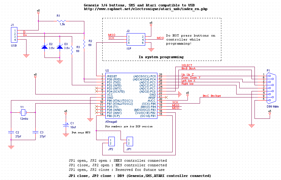
[19:21:08] <Metalsutton> Hey everyone. Can someone please explain to me the purpose of Zenar diodes betwee the ground and the D- , D++ lines to an AVR chip?
[19:21:46] <Metalsutton> Following THIS schematic:
http://www.raphnet.net/electronique/atari_usb/schematic_db9.png
[19:22:44] <Metalsutton> I had created the board and I was trying to troubleshoot why it wasnt working. It wasn't till I removed the Zener diode from pin 2/3 that it started to work.
[19:24:17] <Metalsutton> At first I thought I had maybe purchased defective diodes. I soldered them in and measured with a diode test and current was flowing both ways! I dont think this is normal?
[19:28:29] <Martyn> Nope, dead diode
[19:29:10] <Martyn> Well, wait
[19:29:26] <Martyn> in a Zenier, there is a -specific- breakdown voltage in the reverse direction
[19:29:49] <Martyn> they are used for voltage regulation .. so there should be current in the other direction -at and above- a specific voltage
[19:31:09] <Martyn> Metalsutton: here -
http://sound.westhost.com/appnotes/an008.htm
[19:35:21] <Metalsutton> Cheers for the info
[19:36:11] <Metalsutton> Also, I think they wernt working because when I was at an electronics store I think I may have acidently picked up 3.3v diodes instead of 3.6v. I don't have the docket here anymore so I don't know what I received.
[19:43:53] <skorket> has anyone else been having trouble with arduinio/ftdi and linux?
[19:44:39] <kline> skorket: what in particular? there are a few places it can fall down
[19:44:50] <kline> (feel free to come over into #arduino , btw)
[19:45:31] <skorket> kline, I have an arduino clone from seeed studios and it either immediately, eventually, or when unplugging the device freezes my system
[19:46:06] <kline> sounds like youd be better off asking in a channel for your distro
[19:46:48] <skorket> kline, I have. I've upgraded the kernel multiple times and it seems like it's getting better (as in, it's not freezing the system immediately)...
[19:47:29] <skorket> kline, I also suspect that if it is a software issue, it has to do with the ftdi usb drivers and so would make it a kernel issue, though I'm happy to be proven wrong about that
[19:47:35] <Kevin`> skorket: and what does your serial, bios vga (not x), or netconsole say when it crashes?
[19:47:37] <kline> right. either way, its a linux issues, and ive not seen it before on #arduino
[19:47:48] <kline> but ill stick around
[19:48:41] <skorket> Kevin`, at one point under one version of linux it was eventually spitting out...timeout errors? something about a program not responding for X amount of seconds...khubd or something? Is that what you were asking?
[19:49:04] <Kevin`> skorket: maybe, pastebin it all
[19:50:15] <Kevin`> btw, even though this has to be either a kernel bug or a hardware fault in your desktop, ftdi serial adapters aren't exactly uncommon.. it should have come up before
[19:50:40] <Kevin`> doesn't hurt to fix whatever the problem is though, even if it's a broken serial adapter that's causing it to surface
[19:50:48] <skorket> Kevin`, it was a while ago unfortunately, and when it got into that state I couldn't get the system to respond. I can dmesg or paste logs if you want. Here's my original post:
http://askubuntu.com/questions/109031/system-hangs-after-plugging-in-an-arduino
[19:51:10] <skorket> ubuntu bug report here:
https://bugs.launchpad.net/ubuntu/+source/pcmanfm/+bug/968942
[19:51:58] <Kevin`> skorket: that's why a serial cable is helpful. you kind of need the log while it crashes, and you can't get that locally (netconsole MAY also work)
[19:52:06] <skorket> I've since upgraded to 3.2.15
[19:53:12] <skorket> Kevin`, what do you suggest I do?
[19:54:25] <Kevin`> skorket: is the system log there from after it freezes? that's odd since the system log writing to disk requires the system to be pretty much workin
[19:55:23] <skorket> Kevin`, under one scenario of it freezing I had music playing in the background (with mplayer) but no keyboard or mouse input.
[19:56:08] <skorket> I tried plugging in the device when in a console (not X) and after a couple of minutes (I can't remember how long) it started spitting out messages about khubd not responding
[19:56:12] <Kevin`> I wonder if it's something that could be reproduced by unplugging a device while modem-manager is using it. that obviously happened, but it shouldn't cause a problem (it shouldn't hang, it should fail io)
[19:56:44] <Kevin`> the khubd is probably more important
[19:57:00] <kline> skorket: another thing you could try is holding the reset button on the arduino. that way, we can determine if its FTDI based, or based on the code on the 328
[19:57:45] <kline> (but if it hangs immediately, then its likely FTDI because of the bootdelay on the 328 for the loader)
[19:57:53] <skorket> kline, I've tried unplugging the device when my system has freezed, giving no result. I'm happy to run that test if you think it's fruitful but it'll probably require me to reboot and come back in a few minutes
[19:57:53] <Kevin`> i've actually seen a bug like this before, although it was with a somewhat different device
[19:58:06] <kline> skorket: id hold off on it for now
[19:58:43] <Kevin`> hmm, the ftdi chip shouldn't be disappearing though
[23:21:49] <SuperMig1el> is there a way to upload code while an xbee is connected to the board?